


35
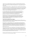
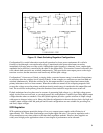
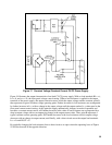
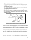
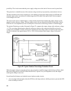
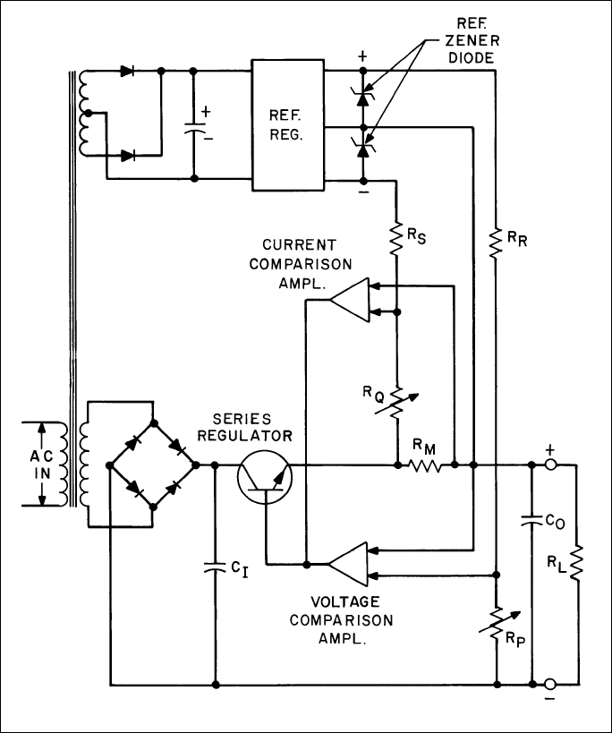
Figure 17. Constant Voltage/Constant Current CV/CC Power Supply
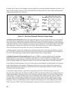
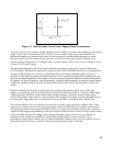
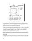
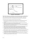
Figure 18 illustrates the output characteristic of an ideal CV/CC power supply. With no load attached (RL= ∞),
I
OUT
= 0, and
EOUT
= E
S
, the front panel voltage control setting. When a load resistance is applied to the output
terminals of the power supply, the output current increases, while the output voltage remains constant; point D
thus represents a typical constant voltage operating point. Further decreases in load resistance are accompanied
by further increases in I
OUT
with no change in the output voltage until the output reaches Is, a value equal to the
front panel current control setting. At this point the supply automatically changes its mode of operation and
becomes a constant current source; still further decreases in the value of load resistance are accompanied by a
drop in output voltage with no accompanying change in the output current value. Thus, point B represents a
typical constant current operating point. Still further decreases in the load resistance result in output voltage
decreases with no change in output current, until finally, with a short circuit across the output load terminals.
I
OUT
= Is and EOUT = 0.
By gradually changing the load resistance from a short circuit to an open circuit the operating locus of Figure
18 will be traversed in the opposite direction.