


28
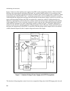
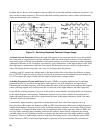
Included, but not shown, in the modulator chip are additional circuits that establish a minimum "dead time" (off
time) for the switching transistors. This ensures that both switching transistors cannot conduct simultaneously
during maximum duty cycle conditions.
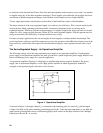
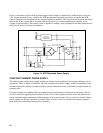
Figure 10. Switching Regulated Constant Voltage Supply
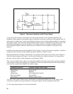
Ac Inrush Current Protection. Because the input filter capacitors are connected directly across the rectified
line, some form of surge protection must be provided to limit line inrush currents at turn-on. If not controlled,
large inrush surges could trip circuit breakers, weld switch contacts, or affect the operation of other equipment
connected to the same ac line. Protection is provided by a pair of thermistors in the input rectifier circuit. With
their high negative temperature coefficient of resistance, the thermistors present a relatively high resistance
when cold (during the turn-on period), and a very low resistance after they heat up.
A shorting strap (J1) permits the configuration of the input rectifier-filter to be altered for different ac inputs.
For a 174-250Vac input, the strap is removed and the circuit functions as a conventional full-wave bridge. For
87-127Vac inputs, the strap is installed and the input circuit becomes a voltage doubler.
Switching Frequencies, Present and Future. Presently, 20KHz is a popular repetition rate for switching
regulators because it is an effective compromise with respect to size, cost, dissipation, and other factors.
Decreasing the switching frequency would bring about the return of the acoustical noise problems that plagued
earlier switching supplies and would increase the size and cost of the output inductors and filter capacitors.
Increasing the switching frequency, however, would result in certain benefits; including further size reductions
in the output magnetics and capacitors. Furthermore, transient recovery time could be decreased because a
higher operating frequency would allow a proportional decrease in the output inductance, which is the main
constraint in recovery performance.
Unfortunately, higher frequency operation has certain drawbacks. One is that filter capacitors have an
Equivalent Series Resistance and Inductance (ESR and ESL) that limits their effectiveness at high frequencies.
Another disadvantage is that power losses in the switching transistors, inductors, and rectifier diodes increase
with frequency. To counteract these effects, critical components such as filter capacitors with low ESRs, fast
recovery diodes, and high-speed switching transistors are required. Some of these components are already
available, others are not. Switching transistors are improving, but remain one of the major problems at high
frequencies. However, further improvements in high-speed switching devices, such as the new power Field
Effect Transistors (FETs) would make high frequency operation and its associated benefits, a certainty for