


44
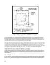
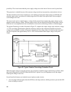
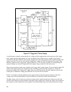
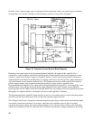
Figure 24. "Piggy-back" Power Supply
As an illustrative example, assume that the low voltage rectifier supplying the series transistor of the "piggy-
back" supply develops approximately 40 volts, and that the main voltage source is capable of providing a
maximum of 300 volts. With 20 volts normally dropped across the series regulator, the maximum output of this
supply would be 320 volts; 20 volts from the "piggy-back" supply and 300 volts from the main source. Thus,
the series regulator of the "piggy-back" supply would have a ± 20 volt range available for accomplishing the
dynamic changes necessary to compensate for the output voltage variations of the main source.
Short-circuit protection for the series regulator in the "piggy-back" supply (Figure 24) is provided by diode CR
P
which, if the output terminals are shorted, provides a discharge path for rectifier capacitor C
M
. Since CR
P
prevents the output of the "piggy-back" supply from ever reversing polarity, the series regulator will never be
called upon to withstand a voltage greater than the 40 volts from its own rectifier.
Fuse F1 is included so that the path between the output terminals and the rectifying elements of the main
voltage source will be opened under overload conditions, to protect the rectifiers and transformer.
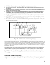
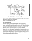
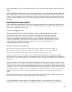
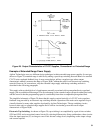
The high voltage control circuit does not derive its input control signal from the total voltage across the load
resistor or the voltage across the terminals of the high voltage supply itself. Instead, the control circuit monitors
the voltage across the combination series regulator and current monitoring resistor and maintains this voltage