


48
Its ohmic value is large enough to give an adequate current monitoring voltage, yet small enough to minimize
its temperature rise (and the resulting resistance change) caused by its own power dissipation.
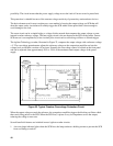
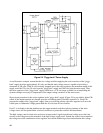
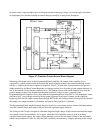
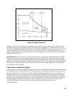
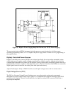
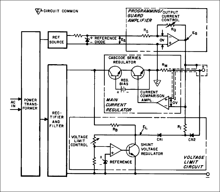
Figure 27. Precision Current Source Block Diagram
Returning to the guard duties of the Programming/Guard Amplifier, the output of this amplifier (E
G
) is
connected to a guard conductor which surrounds the positive output terminal, the current monitoring resistor,
and the (+) input to the Current Comparison Amplifier. Since E
G
is held at the same potential as the positive
output terminal by the Main Current Regulator, no leakage current flows from the positive output terminals (or
any of the internal circuit elements connected to it). The leakage currents that would normally flow from the
positive output circuitry flow instead from the guard conductor, whose current is supplied by the
Programming/Guard Amplifier. Notice that since the Programming/Guard Amplifier is a low impedance source
referenced to (C), any leakage current fed by the guard originates from circuit common via this amplifier,
bypassing RM--only the output current flows through RM. In this way leakage current flowing directly between
the supply's two output terminals is eliminated, and precise load regulation is obtained.
The Programming/Guard Amplifier output may also be used as a convenient point to connect indicating meters,
since the current to drive these meters will not affect the regulated output current I
O.
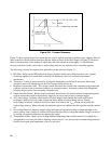
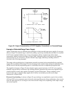
The Voltage Limit Circuit is designed to eliminate dangerous high-voltage or high-current transients that might
occur under certain load conditions. For example. when the load is suddenly removed from an ordinary
constant-current power supply, the output voltage attempts to rise to the raw supply voltage of the instrument,
which can be hundreds of volts. Or, when the load is suddenly reconnected to a supply operating in the voltage