


73
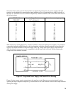
Some idea of how easily even the shortest leads can degrade the performance of a power supply at the load
terminals can be obtained by comparing the output impedance of a well-regulated power supply (typically of
the order of 1 milliohm or less at dc and low frequencies) with the resistance of the various wire sizes listed in
the following chart.
AWG (B & S)
WIRE SIZE
Annealed Copper Resistance at
20°C milliohms/ft.
Nominal current rating (amps)*
22 16.1 5
20 10.2 7
18 6.39 10
16 4.02 13
14 2.53 20
12 1.59 25
10 0.999 40
8 0.628 55
6 0.395 80
4 0.249 105
2 0.156 140
0 0.0993 195
00 0.0779 260
* Single conductor in Free Air at 30°C with rubber or thermoplastic insulation
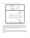
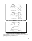
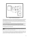
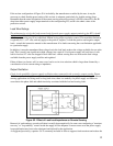
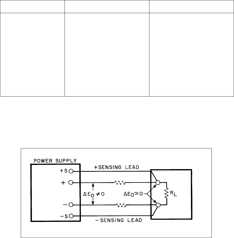
With remote error sensing (Figure 47), a feature included on nearly all Agilent power supplies, it is possible to
connect the feedback amplifier directly to the load terminals so that the regulator performs its function with
respect to the output terminals of the power supply. Thus, the voltage at the power supply output terminals
shifts by whatever amount necessary to compensate for the IR drop in the load leads, thereby retaining the
voltage at the load terminals constant.
Figure 47. Regulated Power Supply with Remote Error Sensing
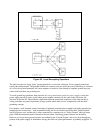
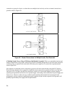
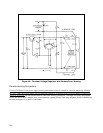
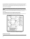
Figure 48 shows remote sensing connections to the regulator circuit. Remote error sensing simply involves
operating the input comparison amplifier Q1 with reference to the load terminals instead of the output terminals
of the power supply.