


117
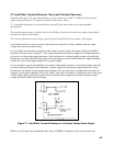
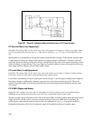
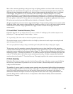
Most of the comments pertaining to the ground loop and pickup problems associated with constant voltage
ripple and noise measurement also apply to the measurement of constant current ripple and noise. Figure 82
illustrates the most important precautions to be observed when measuring the ripple and noise of a constant
current supply. The presence of a 2f
L
waveform on the oscilloscope is normally indicative of a correct
measurement method. A waveshape having a fundamental component at f
L
is typically associated with an
incorrect measurement setup. As before, the basic measuring instrument is an oscilloscope. The measurement of
CC noise spikes is similar to CV noise spikes as discussed previously, except that an appropriate load resistor
RL and current monitoring resistor RM must be included, as illustrated in Figure 82C.
The peak-to-peak/rms conversion factors suggested by Figure 73 and comments in the previous sections of this
Handbook dealing with constant voltage pickup and ground loop effects, as well as the section dealing with the
measurement of constant voltage ripple and noise, apply in full to constant current ripple and noise
measurements.
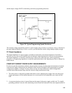
CC Load Effect Transient Recovery Time
Definition: The time "X" for output current recovery to within "Y" milliamps of the nominal output current
following a "Z" amp step change in load voltage -- where:
"Y" is generally of the same order as the load regulation specification.
The nominal output current is defined as the dc level half way between the static output current before and
after the imposed load change.
"Z" is the specified load voltage change, normally equal to the full load voltage rating of the supply.
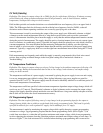
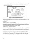
The test set-up used for measuring constant voltage transient recovery time should be used for measuring
constant current transient recovery time except that the contacts of the mercury relay are connected in parallel
rather than in series with the load resistance (refer to Figure 79). The waveforms obtained are similar to those
indicated on Figure 73, but keep in mind that "Y" in millivolts must be converted to milliamps by dividing the
value of "Y" by the ohmic value of the current monitoring resistor, R
M
. All other comments and conditions
mentioned previously under CV Transient Recovery Time apply equally to the constant current measurement.
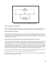
CC Drift (Stability)
Definition: The change in output current for the first 8 hours following a 30 minute warm-up period. During
the interval of measurement all parameters such as load resistance, ambient temperature, and input line
voltage are held constant.
The stability of a power supply in constant current operation must be measured while holding the temperature
of the power supply and the current monitoring resistor R
M
as constant as possible. Variations of the voltage
across this current monitoring resistor over the specified 8-hour interval are measured on the digital or
differential voltmeter and may be recorded on a strip chart recorder. Since such voltage measurements are
generally being made at a rather low level, it is important to check that the stability of the measurement
instruments is adequate.