


114
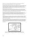
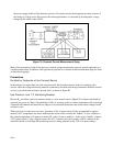
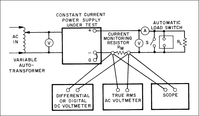
the power supply which will be shorted to ground. All constant current measurements are made in terms of
the change in voltage across this resistor; the current performance is calculated by dividing these voltage
changes by the ohmic value of RM.
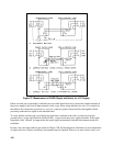
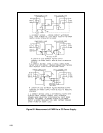
Figure 79. Constant Current Measurement Setup
Many of the precautions listed for the previous constant voltage measurement setup are equally applicable to a
constant current setup. In addition, other precautions peculiar to a constant current measurement setup are listed
on the following pages.
Precautions
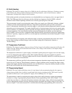
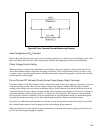
R
M
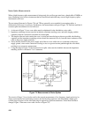
Must be Treated as a Four-Terminal Device
In the manner of a meter shunt, the load current must be fed from the extremes of the wire leading to this
resistor, while the voltage monitoring terminals connected to the three measuring instruments should be located
as close as possible to the resistance portion itself, as shown in Figure 80.
Use Precision, Low T. C. Monitoring Resistor.
Resistor R
M
should be a precision ammeter shunt or a wire-wound resistor (20ppm/°C or better) and should be
operated at a power less than 1/10 (preferably 1/100) of its rating so that its surface temperature will not be high
compared with ambient and therefore not subject to slow thermal fluctuations that cause similar changes in the
resistance value.
With typical wire-wound power resistors, operation at 10% of power rating will be accompanied by approx-
imately a 50°C temperature rise above ambient at the surface of the resistor; the "bobble," or slow variation in
this surface temperature, will amount to about 20% of the rise above ambient -- in this case a "bobble" of about
10°C (peak-to-peak). Using a 20ppm resistor, this 10°C variation will cause roughly a 0.02% variation in the
measured current, even though the monitoring resistor is being operated at only 1/10 of its power rating !