


40
possibility. The circuit insures that the power supply voltage across the load will never exceed a preset limit.
This protection is valuable because of the extreme voltage sensitivity of present-day semiconductor devices.
The basic elements used in most crowbars are: some method of sensing the output voltage, an SCR that will
short the output, and a circuit that will reliably trigger the SCR within a time period that is short enough to
avoid damage to the load.
The sense circuit can be a simple bridge or voltage divider network that compares the output voltage to some
internal crowbar reference voltage. The best trigger circuit is the one that turns the SCR on the fastest. Fastest
SCR turn-on is accomplished by a fast rise-time pulse circuit such as a blocking oscillator or Schmitt trigger.
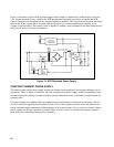
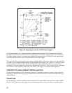
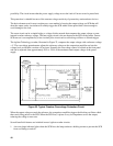
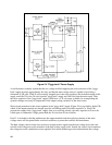
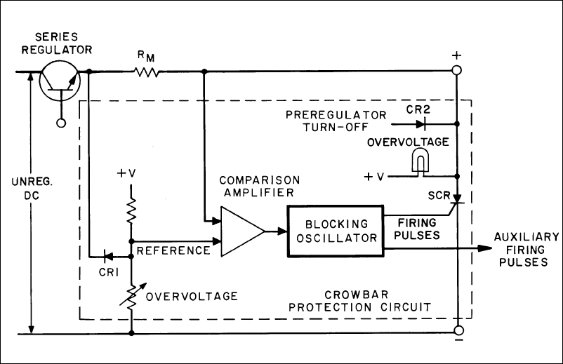
The Agilent Technology crowbar, illustrated in Figure 22, compares the output voltage with a reference voltage
+ V. The overvoltage potentiometer adjusts the reference voltage on the comparison amplifier and sets the
voltage level at which the crowbar will activate. Normally the overvoltage control is located on the front panel
and can be adjusted from approximately 20% to 120% of the maximum rated output voltage of the power
supply.
Figure 22. Typical Crowbar Overvoltage Protection Circuit
When the output voltage exceeds the reference, the comparison amplifier triggers the blocking oscillator which
then sends firing pulses to the SCR. When the SCR fires, it places a very low impedance across the output,
reducing the voltage to near-zero.
Several beneficial features are included in most Agilent crowbar circuits:
1. An overvoltage indicator lights when the SCR fires; the lamp conducts a holding current to prevent the SCR
from oscillating on and off.