


57
Additional circuits are also included to facilitate operation within the systems environment. The additional
circuitry performs interface, isolation, storage, overcurrent protection, and status feedback functions as
explained in subsequent paragraphs.
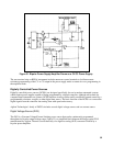
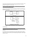
Interface and Isolation. Each input and output signal, to and from a DCPS, passes through interface and
isolation circuits. Interface circuits are designed to match the unit to a variety of controllers. Isolation circuits
isolate the digital input from the analog output voltage allowing the output to be floated if desired. Isolation
also prevents troublesome loops between the output ground and controller ground and prohibits potentially
destructive current surges which could occur if some point in the load were inadvertently grounded.
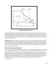
Storage. The digital voltage and current programming input data are transferred into integrated-circuit storage
buffers upon receipt of the storage pulse from the controller. Once the data is stored, the controller can perform
other tasks without the need for maintaining the input data. This increases controller operating efficiency and
even allows "party-line" operation where one set of data lines can be used to program several DCPS.
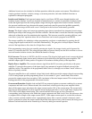
The storage capability also minimizes voltage programming overshoots or undershoots by ensuring that all
voltage program inputs reach the D/A converter simultaneously. The gate pulse is delayed 50µsec from the
arrival of the input data to allow time for all input lines to settle.
If the programming source does not normally generate gate signals, the storage circuits can be bypassed by
means of a switch on the DVS. The voltage program data now passes directly into the D/A converter as soon as
received from the isolation circuits, but without the benefit of storage.
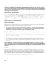
D/A Converter. The heart of a DCPS is the D/A converter. This bi-polar, high-speed circuit converts the digital
voltage programming inputs into an analog reference signal which drives the precision power amplifier. The
reference output signal is either positive or negative in accordance with the polarity of the input data.
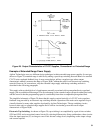
Bipolar Power Amplifier. The accurate reference signal from the D/A converter goes directly to the power
amplifier. To preserve the accuracy of the input signal, large amounts of negative feedback are used in the
amplifier circuits. The amplifier can be programmed either side of, or through, zero without "notch" effects or
the use of polarity switches.
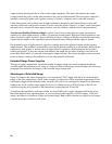
The power amplifier has a self-contained voltage limit circuit which prevents the output voltage from exceeding
110% of rating despite possible programming errors. It also contains a "gross" current limit circuit which
prevents the output current from exceeding 110% (maximum) of the rated output current. This circuit provides
backup protection for the programmable overcurrent circuits.
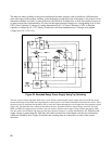
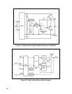
Overcurrent Protection. Both the load and the DVS are protected against overcurrent conditions by a current
comparator and latch circuit. When activated, this circuit sends a latch signal to the power amplifier which
shuts off the output stages and reduces the output current to under 10% of the current rating. The current latch
trip point can be programmed, by three external current latch program bits, to one of eight values ranging from
2% to 100% of the output current rating. The current latch bits from storage are first converted to a
corresponding analog reference value within the current comparator and latch circuit. Next, this reference value
is compared with a sample of the output current (IOUT). If the output current equals or exceeds this reference
value, a current overload condition exists. Approximately 5µsec after a current overload is detected; a latch
signal is generated to reduce the output current. Should the load require a heavy initial current, the delay period
between overload and latch can be extended up to 2msec by adding an external capacitor.