


54
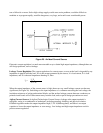
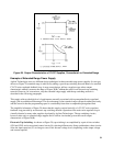
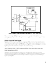
The extended range power supply overcomes the latter problem through the use of series regulating transistors
with higher voltage ratings and with thermally improved heat sinks. The heat sinks allow the series transistors
to be properly cooled during the worst case conditions that are encountered during rapid down-programming. In
addition, a special transistor circuit (not shown on Figure 29) provides for a more rapid discharge of the output
capacitor during down-programming.
Bipolar Power Supply/Amplifier
In some applications a power supply is required that has a faster programming speed than standard designs (see
Remote Programming Chapter for programming speed limitations). Still other applications require a power
supply that can be controlled continuously through zero over a wide span in either the positive or negative
direction. Bipolar Power Supply/Amplifiers (BPS/As), which utilize the operational amplifier concept of power
supplies, have been developed to meet these needs. A BPS/A is not only a high speed, programmable power
supply but can also be used as direct-coupled amplifier with low output distortion and a bandwidth from dc to
as high as 40KHz (in certain operating modes).
Bipolar Power Supply
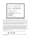
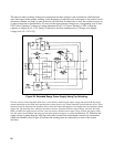
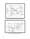
Figure 31 shows a simplified representation of the instrument drawn as a CV/CC power supply. Note that this
circuit differs from the typical CV/CC power supply of Figure 17 in that:
1. The regulating elements consist of two series transistors connected in a push-pull, pseudocomplementary
configuration (Q1 and Q2 are actually npn's). Q1 is connected to a positive rectifier and controls positive
outputs while Q2 (connected to a negative rectifier) controls negative outputs.
2. A bipolar CV reference source is used instead of a unipolar one to allow a bipolar output in the constant
voltage operating mode.
3. Two current comparison amplifiers and an associated bipolar reference source, are used to provide a bipolar
output in the constant current mode.
4. The output capacitor has been eliminated to increase programming speed. Additional modifications, not
shown in Figure 31, insure that the power supply will remain stable for capacitive, resistive, or inductive
type loads.
Aside from the above differences, basic operation of this bipolar power supply is very similar to most other
CV/CC supplies. The CV or CC comparison amplifiers compare the output voltage (or current) with the bipolar
reference and generate amplified error signals that control the conduction of the applicable regulating transistor
(Q1 or Q2).
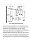
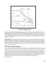
Amplifier
Figure 32 shows the BPS/A redrawn as an amplifier. Transistors Q1 and Q2 are arranged in a single-ended,
push-pull configuration, and the operational amplifier aspects are more readily suggested by this configuration.
For simplicity, the constant current control circuits are not included in Figure 32. In the amplifier mode, the
BPS/A controls the gain of an externally applied dc or ac signal. In Figure 32, an external ac input signal has
been substituted for the internal bipolar reference supply shown in Figure 31.