


27
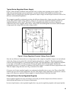
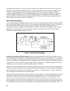
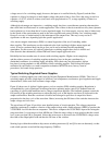
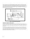
voltage across it. In a switching supply, however, the input ac is rectified directly (Figure 9) and the filter
capacitor is allowed to charge to a much higher voltage (the peaks of the ac line). Since the energy stored in a
capacitor = 0.5CV2, while its volume (size) tends to be proportional to CV, storage capability is better in a
switching supply.
Although its advantages are impressive, a switching supply does have some inherent operating characteristics
that could limit its effectiveness in certain applications. One of these is that its transient recovery time (dynamic
load regulation) is slower than that of a series regulated supply. In a linear supply, recovery time is limited only
by the speeds of the semiconductors used in the series regulator and control circuitry. In a switching supply,
however, recovery is limited mainly by the inductance in the output filter. This may or may not be of
significance to the user, depending upon the specific application.
Also, electro-magntic interference (EMI) is a natural byproduct of the on-off switching within
these supplies. This interference can be conducted to the load (resulting in higher output ripple and
noise), it can be conducted back into the ac line, and it can be radiated into the surrounding
atmosphere. For this reason, all Agilent Technologies switching supplies have built-in shields and
filter networks that substantially reduce EMI and control output ripple and noise.
Reliability has been another area of concern with switching supplies. Higher circuit complexity
and the relative newness of switching regulator technology have in the past contributed to a
diminished confidence in switching supply reliability. Since their entry into this market, Agilent
has placed a strong emphasis on the reliability of their switching supplies. Field failures have been
minimized by such factors as careful component evaluation, MTBF life tests, factory "burn-in"
procedures, and sound design practices.
Typical Switching Regulated Power Supplies
Currently, switching supplies are widely used by Original Equipment Manufacturers (OEMs). This class of
switching supply provides a high degree of efficiency and compactness, moderate-to-good regulation and ripple
characteristics, and a semi-fixed constant voltage output.
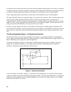
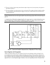
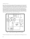
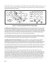
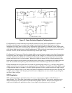
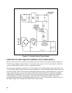
Figure 10 shows one of Agilent’s higher power, yet less complex, OEM switching supplies. Regulation is
accomplished by a pair of push-pull switching transistors operating under control of a feedback network
consisting of a pulse width modulator and a voltage comparison amplifier. The feedback elements control the
ON periods of the switching transistors to adjust the duty cycle of the bipolar waveform (E) delivered to the
output rectifier/filter. Here the waveform is rectified and averaged to provide a dc output level that is
proportional to the duty cycle of the waveform. Hence, increasing the ON times of the switches increases the
output voltage and vice-versa.
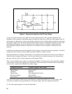
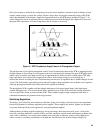
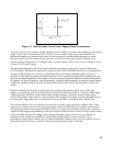
The waveforms of Figure 10 provide a more detailed picture of circuit operation. The voltage comparison
amplifier continuously compares a fraction of the output voltage with a stable reference (EREF) to produce the
VCONTROL level for the turn-on comparator. This device compares the VCONTROL input with a triangular
ramp waveform (A) occurring at a fixed 40KHz rate. When the ramp voltage is more positive than the control
level, a turn-on signal (B) is generated. Notice that an increase or decrease in the VCONTROL voltage varies
the width of the output pulses at B and thus the ON time of the switches.
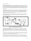
Steering logic within the modulator chip causes switching transistors Q1 and Q2 to turn on alternately, so that
each switch operates at one-half the ramp frequency (20KHz).