


107
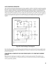
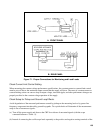
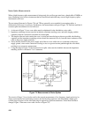
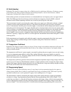
measurements where both the power supply and the oscilloscope case are connected to ground (e. g., if both are
rack-mounted), it may be necessary to use a differential scope with floating input as shown in Figure 72C. If
desired, two single-conductor shielded cables may be substituted in place of the shielded two-wire cable.
Because of its common mode rejection, a differential oscilloscope displays only the difference in signal
between its two vertical input terminals, thus ignoring the effects of any common mode signal introduced
because of the difference in the ac potential between the power supply and scope case. Before using a
differential input scope in this manner, however, it is imperative that its common mode rejection be verified by
shorting together the two input leads at the power supply and observing the trace on the CRT. If this trace is a
straight line, the scope is properly ignoring any common mode signal present. If it is not a straight line, then the
scope is not rejecting the ground signal and must be realigned in accordance with the manufacturer's
instructions.
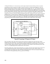
To be absolutely certain that the measurement setup is free from extraneous signals, turn off the power supply
and, with the scope connected across +S and -S terminals, ascertain that no signals are present on the CRT. The
presence of noise signals under these conditions is indicative of pickup on the leads between the power supply
and the scope.
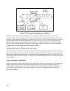
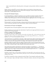
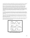
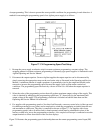
Figure 73 shows the relationship between the peak-to-peak and rms values of three common waveforms. The
output ripple of a dc power supply usually approximates the sawtooth of Figure 73B, which is 1/3.464 of the
peak-to-peak value displayed on the oscilloscope. The square wave is included in Figure 73 because it has the
highest possible peak to rms ratio.
Thus, the rms ripple and noise present on the output terminals of a power supply cannot be greater than 1/2 the
peak-to-peak value measured on the oscilloscope. In most cases, the rms ripple on Agilent power supplies is
between 1/3 and 1/4 of the peak-to-peak value.
Figure 73. Three Ideal Ripple Waveshapes