


98
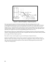
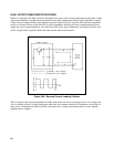
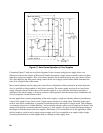
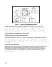
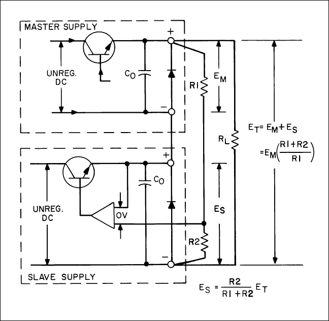
Figure 67. Auto-Series Operation of Two Supplies
Comparing Figure 67 with previous block diagrams for the constant voltage power supply, there is no
difference in the circuit location of Resistor R2 and the front panel voltage control normally found in Agilent
laboratory type power supplies. Thus, Auto-Series operation can be achieved using only one external resistor
(R1) and employing the front panel voltage control on the slave supply as the element which determines the
ratio of its voltage to that of the master.
Mixed model numbers may be employed in Auto-Series combination without restriction, provided that each
slave is specified as being capable of Auto-Series operation. The master supply need not be an Auto-Series
supply since the internal circuit aspects of the master supply in no way affect the AutoSeries principle of
operation. If the master supply is set up for constant current operation, then the master-slave combination will
act as a composite constant current source.
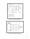
In some applications, remote programming of the master supply is employed, thereby achieving simultaneous
control of the output of two sources from a single remote resistance or voltage input. When the center tap of
such an Auto-Series combination is grounded coordinated positive and negative voltages result. This technique
is commonly referred to as "rubber-banding," and an external reference source may be employed if desired. Any
change of the internal or external reference source (e. g., drift, ripple) will cause an equal percentage change in
the outputs of both the master and slave supplies. This feature is of considerable use in any application, where
the load requires a positive and a negative power supply and is less susceptible to an output voltage change
occurring simultaneously in both supplies than to a change in either supply alone.