


97
of current monitoring resistors in the master and slave supplies, the output current contribution will always be
equal regardless of the output voltage or current requirement of the load.
Normally, only supplies having the same model number should be connected for Auto-Parallel operation, since
the two supplies must have the same voltage drop across the current monitoring resistor at full current rating.
As is also true of Auto-Series and Auto-Tracking operation, no internal wiring changes are necessary. All that is
required is a screwdriver to change the strapping pattern on the terminals of the rear barrier strip, and one extra
lead running from the barrier strip of each slave supply to another supply in the same master-slave system.
SERIES OPERATION
Series operation of two or more Agilent power supplies can be accomplished up to the output isolation rating
(usually 300 volts off ground) of any one supply. Series connected supplies can be operated with one load
across both supplies or with a separate load for each supply. All Agilent semiconductor power supplies have
reverse polarity diodes connected across the output terminals so that if operated in series with other power
supplies, reverse polarity will not occur across the output terminal of any supply if the load is short-circuited or
if one power supply is turned on separately from its series partners.
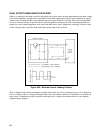
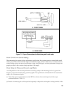
AUTO-SERIES OPERATION
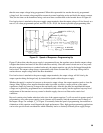
Auto-Series or automatic series operation of power supplies permits equal or proportional voltage sharing under
all load conditions, with complete control of the AutoSeries ensemble being obtained from the master supply
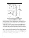
alone. Figure 67 illustrates the circuit principle involved. The slave supply is connected in series with the
negative output terminal of the master supply, and a voltage divider (R1 and R2) is placed across the series
voltage span. One input of the comparison amplifier of the slave supply is connected to the junction of these
two resistors while the other input is connected to the positive output terminal of the slave. Since normal
feedback action of the slave supply is such as to maintain a zero error between the two comparison amplifier
inputs, the slave supply will contribute a fraction of the total output voltage determined by the voltage divider
R1 and R2.
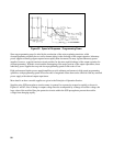
For example, if these two resistors are equal, the slave supply will contribute half the total output voltage with
the master supply contributing the other half. Notice that the percent of the total output voltage contributed by
each supply is independent of the magnitude of the total voltage. When using fixed resistors R1 and R2, the
front panel voltage control of the slave supply will be inoperative. Turning the voltage control of the master
supply will result in a continuous variation of the output of the series combination, with the contribution of the
master's output voltage to that of the slave's voltage always remaining in the ratio of R1 to R2.
Since any variation in the resistance value of R1 and R2 will result in a change in the voltage divider ratio and
hence the output of the slave supply, it is important that both these resistors have a low temperature coefficient
(20 ppm/°C or better) and have a power rating at least 10 times their actual dissipation. Resistors R1 and R2
should be selected so that at the nominal operating levels the current through them will be of the order of 1 to
5mA.