


64
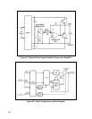
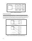
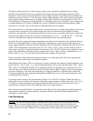
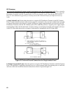
The battery symbol represents an ideal constant voltage source with perfect regulation and zero output
impedance at all frequencies, but every regulated power supply has some small output impedance at high
frequencies. Thus a more exact circuit model for a power supply includes an equivalent source resistance and
inductance as shown in Figure 37. R
S
is the power supply output impedance at dc, and is found by dividing the
load regulation by the current rating; for example, a power supply which has a load regulation of 10mV for a
full load change of 10 amps has an equivalent R
S
of 1 milliohm, a typical value. Similarly, a power supply with
an output impedance of 0.2 ohms at 100KHz and 2 ohms at 1MHz has an equivalent high frequency output
inductance L
S
of 0.3µH - again a value typical of high performance power supplies.
The connecting lines on a schematic represent ideal connection between two points, but the physical wires used
to connect any two terminals (such as power supply and load) are characterized by distributed resistance,
inductance, and capacitance. For determining necessary load wire sizes, it is usually sufficient to consider only
the equivalent lumped constant series resistance and inductance (L
0
, L1, L2 . . . and R
0
, R1, R2. . .). Given the
wire size and length, these lumped equivalents can be determined from wire tables and charts.
In general, the power supply performance degradation seen at the load terminals becomes significant whenever
the wire size and length result in a load wire impedance comparable to or greater than the equivalent power
supply output impedance. With one load, this degradation can be evaluated by comparing 2Ro with Rs, and 2Lo
with Ls. The total impedance seen by the load is Z
T
= (R
S
+ 2R
0
) + jω (Ls + 2Lo), and the variation of the dc
load voltage caused by a sinusoidal variation of load current is Eac = Iac ZT. If load current variations are more
pulse-or step-shaped than sinusoidal, then the resulting load voltage "spike" will have a magnitude of e
L
= L
T
(di/dt), where L
T
= L
S
+ 2L
0
, and di/dt is the maximum rate of change of load current.
If these calculations indicate that the resulting variations in dc voltage provided to the load are greater than
desired, then shorter and/or larger load leads are required.
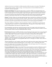
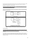
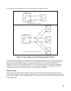
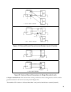
With multiple loads (Figure 37B), it is necessary to consider separately the common or mutual impedance seen
by the loads, R
S
+ 2R
0
) + jω (L
S
+ L
0
), and the added impedance seen by each load individually, 2(R1 + jω L1),
2(R2 + jωL2), etc. Remember that the mutual impedance presents an opportunity for a variation of one load
current to cause a dc voltage variation at another load. If the loads are pulse or digital circuits, false triggering
may result. Similarly, if one load is the output stage of a high gain amplifier, and another load contains low
level stages feeding the same signal path, unintentional feedback may occur via this mutual impedance, with
resulting amplifier oscillation.
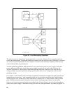
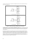
Connecting remote sensing to the load terminals of Figure 37A or the DT's of Figure 37B has the effect of
reducing R
0
by a factor equal to the loop gain of the power supply regulator, usually of the order of 10
3
, 10
4
, or
10
5
. However, remote sensing does not in general alter the effective value of L
0
seen by the load, since L
0
predominates at frequencies above the bandwidth of the power supply regulator.
Since remote sensing affords little or no reduction in the effective load wiring impedance at high frequencies,
some amount of capacitive load decoupling is sometimes desirable, particularly when multiple loads are
connected to a power supply.
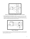
Load Decoupling
A local decoupling capacitor, if required, should be connected across each pair of load and distribution
terminals. This reduces the high frequency impedance seen by any individual load looking back toward the
power supply, and reduces high frequency mutual coupling effects between loads fed from the same
supply. The use of load decoupling capacitors is most often employed with multiple loads drawing pulse
currents with short rise times. Without local decoupling these current changes can cause spikes which