


108
Noise Spike Measurements
When a high frequency spike measurement is being made, the oscilloscope must have a bandwidth of 20MHz or
more. Measuring noise with an instrument that has insufficient bandwidth may conceal high frequency spikes
detrimental to the load.
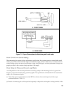
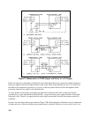
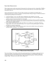
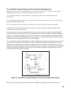
The test setups illustrated in Figures 72A and 72B are generally not acceptable for measuring spikes; a
differential oscilloscope is necessary. Furthermore, the measurement concept of Figure 72C must be modified if
accurate spike measurement is to be achieved:
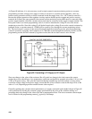
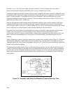
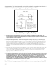
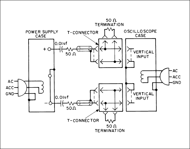
1. As shown in Figure 74, two coax cables must be substituted for the shielded two-wire cable.
2. Impedance matching resistors must be included to eliminate standing waves and cable ringing, and the
capacitors must be connected to block the dc current path.
3. The length of the test leads outside the coax is critical and must be kept as short as possible; the blocking
capacitor and the impedance matching resistor should be connected directly from the inner conductor of the
cable to the power supply terminals.
4. Notice that the shields of the power supply end of the two coax cables are not connected to the power
supply ground, since such a connection would give rise to a ground current path through the coax shield,
resulting in an erroneous measurement.
5. Using the setup in Figure 74, the measured noise spike values must be doubled, because the impedance
matching resistors constitute a 2-to-1 attenuator.
Figure 74. Measurement of Noise Spikes
The circuit of Figure 74 can also be used for the normal measurement of low frequency ripple and noise, by
simply removing the four terminating resistors and the blocking capacitors and substituting a higher gain
vertical plug-in in place of the wide-band plug-in required for spike measurements. Notice that with these
changes, Figure 74 becomes a two-cable version of Figure 72C.