


52
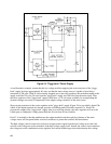
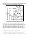
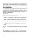
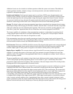
The main secondary winding of the power transformer has three sections, each of which has a different turns
ratio with respect to the primary winding. At the beginning of each half-cycle of the input ac, the control circuit
determines whether one, both, or none of the triacs will be fired. If neither triac is fired, the rectifier receives an
ac input voltage that is determined by N1 turns and the input capacitor charges to a corresponding level. If triac
CR2 is fired, capacitor Cl charges to voltage determined by N1 + N2 turns. Similarly, if CR1 is fired the
capacitor is charged by N1 + N3. Finally, if both triacs are fired simultaneously, Cl charges to its highest
voltage level (N1 + N2 + N3).
Figure 29. Extended Range Power Supply Using Tap Switching
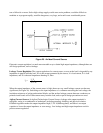
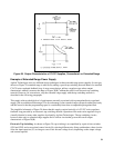
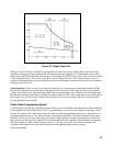
The triac control circuits determine which triac is to be fired by monitoring the output voltage and current (IR drop across
current monitoring resistor, RM) and comparing these values against a set of three internally derived reference levels. These
reference levels are translated into boundary lines to allow the output characteristic to be mapped into four operating regions
(Figure 30). The boundary lines, which are invisible to the user, are named VOD for output voltage "decision" line, and
IOD1 and IOD2 for output current "decision" lines one and two. Whenever the output voltage is below the sloping VOD
line, the control circuit inhibits both triacs and the input capacitor charges to a voltage determined
by N1. Whenever the
output voltage is greater than the VOD line, the control circuit looks at the output current level to determine
which triac should be fired. Figure 30 indicates the windings that are connected as a result of the current
decisions.