


29
future switching supplies.
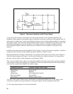
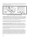
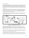
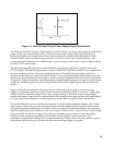
Preregulated Switching Supply. Figure 11 shows another higher power switching supply similar to the circuit
of Figure 10 except for the addition of a triac preregulator. Operation of this preregulator is similar to the
previously described circuit of Figure 7. Briefly, the dc input voltage to the switches is held relatively constant
by a control circuit which issues a phase adjusted firing pulse to the triac once during each half-cycle of the
input ac. The control circuit compares a ramp function to a rectified ac sinewave to compute the proper firing
time for the triac.
Although the addition of preregulator circuitry increases complexity, it provides three important benefits. First,
by keeping the input to the switches constant, it permits the use of lower voltage, more readily available
switching transistors. The coarse preregulation it provides also allows the main regulator to achieve a finer
regulation. Finally, through the use of slow-start circuits, the initial conduction of the triac is controlled;
providing an effective means of limiting inrush current.
Note that the preregulator triac is essentially a switching device and, like the main regulator switches, does not
absorb a large amount of power. Hence, the addition of the preregulator does not significantly reduce the
overall efficiency of this supply.
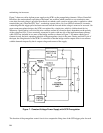
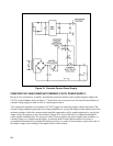
Figure 11. Switching Supply with Preregulator.
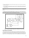
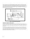
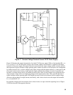
Single Transistor Switching Regulator. At lower output power levels, a one transistor switch becomes
practical. The single transistor regulator of Figure 12 can receive a dc input from either one of two sources
without a change in its basic configuration. For ac-to-dc requirements, the regulator is connected to a line
rectifier and SCR preregulator and for dc-to-dc converter applications it is connected directly to an external dc
source.
Like the previous switching supplies, the output voltage is controlled by varying the ON times of the regulator
switch. The switch is turned on by the leading edge of each 20KHz clock pulse and turned off by the pulse
width modulator at a time determined by output load conditions.
While the regulating transistor is conducting, the half-wave rectifier diode is forward biased and power is
transferred to the output filter and the load. When the regulator is turned off, the "flywheel" diode conducts,
sustaining current flow to the load during the off period. A flywheel diode (sometimes called a freewheeling or