


49
limit mode, a high-current transient can occur if the current regulator saturates while the instrument is still in
voltage limit.
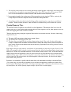
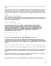
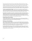
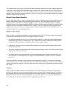
The Voltage Limit Circuit in Constant Current Sources virtually eliminates voltage or current overshoots and
undershoots when going in and out of voltage limit, without adding any significant leakage path across the
output terminals.
Normally, when voltage limiting action is not occurring, the setting of the Voltage Limit Control establishes
across the Shunt Voltage Regulator a preset voltage limit EL which is higher than the positive output voltage
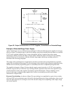
and its twin, the guard voltage EG. Since there is zero volts across the series combination of isolation diode
CR2 and resistor R1 (5 kilohms or less), no current flows through them, and potential EG is also present at their
junction, thus back-biasing isolation diode CR1. (Any small leakage through back-biased diode CR1 flows
through R1 and the output of the Programming/Guard Amplifier, but does not flow into CR2 or the positive
output terminal). The Shunt Voltage Regulator conducts a “standby” current through shunt regulator bias
resistor RB; this current insures that the Shunt Voltage Regulator is operating in its linear region, ready to react
quickly when voltage limiting action is required, thus preventing crossover transients.
If the output voltage exceeds the preset voltage limit value CR1 and CR2 conduct, and the Shunt Voltage
Regulator conducts a portion of the current which otherwise would flow to the load, thus clamping the output
voltage to the preset limit value.
Even during voltage limiting action, E
G
continues to be maintained at a value equal to the potential at the
positive output terminal; both guarding action and the normal control action of the Main Current Regulator
continue, minimizing any output transients which might tend to occur when the output transfers from voltage
limiting to its normal output current mode.
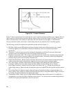
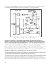
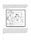
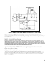
High Output Impedance. The high output impedance of these current sources is a result of several factors,
both electrical and mechanical. The series-regulator transistors are in a cascade configuration, which inherently
has a high output impedance. Since the open-loop gain of the error amplifier is high, the closed-loop output
impedance is greatly increased by feedback.
Output capacitors have been eliminated -- and although the output impedance falls off with frequency because
of the necessary gain and phase compensation in the amplifier circuits, it is much higher than it would be if a
capacitor were connected across the output terminals.
The importance of low output capacitance should not be underestimated. Excessive output capacitance would
cause the output impedance of the current source to fall off with increasing frequency, producing undesirable
transients in rapidly changing loads. Large capacitors store large amounts of energy which, if discharged sud-
denly through the load, may cause damage; negative-resistance devices are particularly susceptible to this kind
of damage. Finally, an output capacitor would slow down the response of the current source to changes in the
external programming signal.
In the interest of keeping the output impedance high, the impedances of internal leakage paths have been made
as high as possible by careful mechanical design and hygienic construction techniques. Leakage, both internal
and external, is further reduced by guarding the positive output terminal.
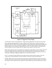
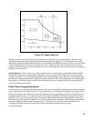
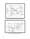
Guarding. In addition to eliminating leakage currents, the guard can also be used to measure the output voltage
without drawing current away from the load. Connecting a voltmeter between the negative output terminal and
the positive output terminal will lower the output impedance, but a voltmeter connected between the negative