


33
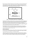
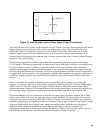
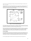
Figure 15. Ideal Constant Current Power Supply Output Characteristic
Any one of the four basic constant voltage regulators can also furnish a constant current output provided that its
output voltage can be varied down to zero, or at least over the output voltage range required by the load.
Besides the regulator, the reference and control circuits required for constant current operation are nearly
identical to those used for constant voltage operation. As a result of these many common elements, most
constant current configurations are combined with a constant voltage circuit in one Constant Voltage/Constant
Current (CV/CC) power supply.
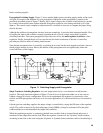
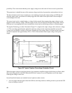
The following paragraphs describe the current feedback loop generally employed in Agilent Technologies
CV/CC supplies. This particular approach to constant current, while sufficiently effective for most applications,
does have limitations that are caused by its simplified nature. For example, although output capacitor Co
minimizes output ripple and improves feedback stability, it also increases the programming response time and
decreases the output impedance of the supply; a decrease in output impedance inherently results in degradation
of regulation. If precise regulation, rapid programming, and high output impedance are required, improvements
on the basic feedback loop are necessary as described under Precision Constant Current Sources later in this
section.
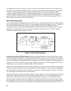
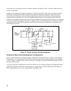
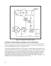
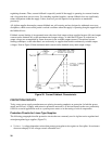
Figure 16 illustrates the elements constituting a basic constant current power supply using a linear type
regulator. As mentioned previously, many of these elements are identical to those of a constant voltage supply
with the only basic difference being in their output sensing techniques. While the constant voltage supply
monitors the output voltage across its output terminals, the constant current supply monitors the output current
by sensing the voltage drop across a current monitoring resistor (RM) connected in series with the load .
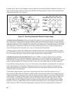
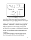
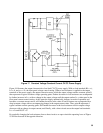
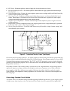
The current feedback loop acts continuously to keep the two inputs to the comparison amplifier equal. These
inputs are the voltage drop across the front panel current control and the IR drop developed by load current I
L
flowing through current monitoring resistor RM. If the two voltages are momentarily unequal, the comparison
amplifier output changes the conduction of the series regulator, which in turn, corrects the load current (voltage
drop across RM) until the error voltage at the comparison amplifier input is reduced to zero. Momentary
unbalances at the comparison amplifier are caused either by adjustment of current control Ra, or by
instantaneous output current changes due to external disturbances. Whatever the cause, the regulator action of
the feedback loop will increase or decrease the load current until the change is corrected.