


75
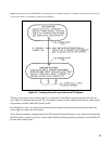
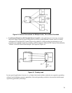
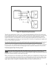
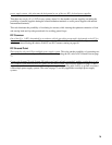
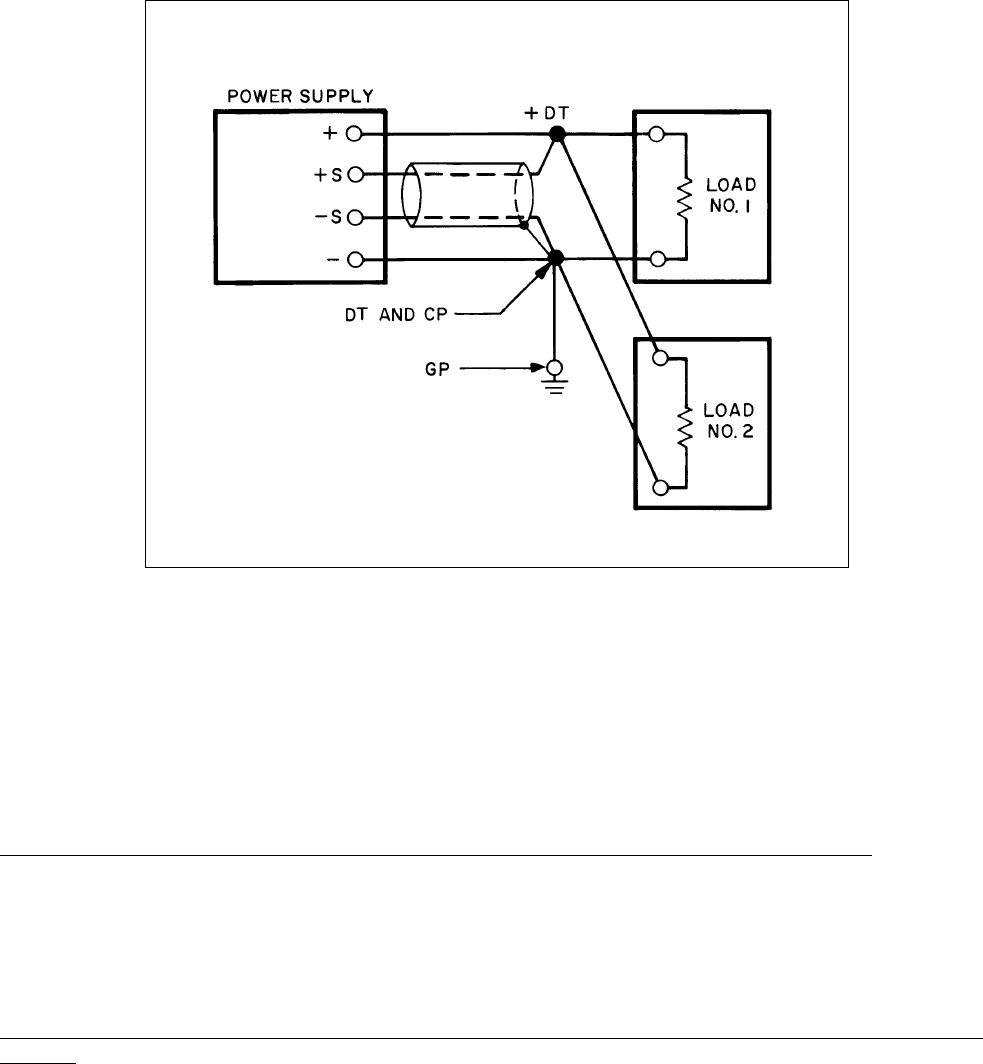
Figure 49. Remote Sensing Connections
Typically, the sensing current is 10mA or less. To insure that the temperature coefficient of the sensing leads
will not significantly affect the power supply temperature coefficient and stability specifications, it is necessary
to keep the IR drop in the sensing conductors less than 20 times the power supply temperature coefficient
(stated in millivolts/°C). This requirement is easily met using readily available small size shielded two-wire
cable--except in applications involving very long sensing leads of unusually well regulated power supplies with
very low TC and stability specifications.
One end of the shield should be connected to the CP and the other end should be left unconnected. In nearly all
cases this method of connecting the sensing shield will minimize ripple at the Load Distribution Terminals.
However, in rare cases a different ground return point for this shield is preferable-- it is important in such cases
to experimentally verify that this relative advantage applies under all possible combinations of load and line.
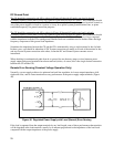
Protecting Against Open Sensing Leads
The possibility of an open remote sensing path, which might occur on a long-term or transient basis, should be
avoided. Such open circuit conditions are likely if the remote sensing path includes any relay, switch, or
connector contacts; any interruption of the connections between the power supply sensing terminals and the DC
Distribution Terminals should be avoided wherever possible.
When a sensing open occurs, the regulator circuit within the supply reacts as though the load voltage were zero-
- usually, the output voltage corrects this deficiency by climbing rapidly toward the maximum rectifier voltage,
a value which is significantly larger than the power supply's maximum rated output voltage. Even if the power
supply output circuitry is designed to withstand this extreme, the chances are that the load is not.