


60
Point (GP).
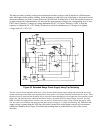
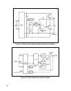
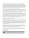
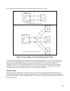
12. The CP should be connected to the GP as shown in Figures 40 through 43 (unless one load is
already grounded), making certain there is only one conductive path between these two points.
72
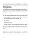
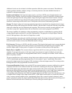
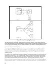
13. Connections between the power supply sensing and output terminals should be removed and
using shielded two-wire cable, the power supply sensing terminals should be connected to the
DC Distribution Terminals as shown in Figure 49.
74
14. One end of the shield should be connected to the CP and the other end should be left
unconnected.
75
15. The possibility of an open remote sensing path, which might occur on a long-term or transient
basis, should be avoided.
75
16. The minimum wire size for the load current leads (from the power supply output terminals to
the DT's) should be determined for remote sensing.
77
17. Check for the possibility of power supply oscillation when connected in the system for remote
sensing.
77
18. Check for proper current limiting operation while the power supply is connected in the system
for remote sensing.
78
Load Connections for Two or More Power Supplies
19. There must be only one point of connection between the dc outputs of any two power supplies
in the multiple power supply system—this point must be designated as one of the two DT's for
both power supplies.
79
20. One of the (N + 1) DT's determined in accordance with the preceding rule is designated as the
CP for the system.
79
21. There must be only one GP per multiple power supply system. 79
22. Connect the System CP to the System GP (unless one load is already grounded), making
certain there is only one conductive path between these two points for the entire system.
79
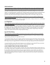
AC POWER INPUT CONNECTIONS
The ac, acc and third wire safety ground continuity should be retained without accidental interchange from ac
power outlet to the power supply input terminals.
Accidental interchanging of ac and safety ground leads may result in the power supply chassis being elevated
to an ac potential equal to the line input voltage. This could result in a potentially lethal shock hazard, if the
chassis is not grounded; or blown fuses, if the chassis is grounded.
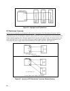
If ac and acc are accidentally interchanged, the power supply switches and fuses are thereby placed in series
with the ground side of the power line instead of the hot side-if the power supply ac line switch is turned off or
the fuse opens, the hot side of the power line will be connected to exposed components within the power
supply.
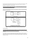
Accidental interchanging of acc and ground leads places the chassis at the acc potential giving rise to
circulating ground currents flowing through the power supply chassis and other associated ground return paths-
the result is often excessive power supply output ripple and malfunction of associated instrument.