


77
If the resistor configuration of Figure 50 is included by the manufacturer or added by the user, it may be
necessary to check that the power rating of this resistor is adequate, particularly for sizable sensing drops.
Remember that the actual dissipation in the remote sensing protection resistors is ED2/R, where ED is the IR
drop from either power supply output terminal to the corresponding DT, and R is the ohmic value of the
protective resistor.
Load Wire Ratings
The minimum wire size for the load current leads (from the power supply output terminals to the DT's) should
be determined. Most well regulated power supplies have an upper limit to the load current IR drop around
which remote sensing may be accomplished without losing proper regulation control. This maximum limitation
is typically 0.5, 1, or 2 volts, and may apply to the positive, negative, or both the positive and negative output
leads - consult the instruction manual or the manufacturer if in doubt concerning the exact limitation applicable
to a particular supply.
In addition, it must be remembered that voltage lost in the load leads reduces the voltage available for use at the
load. This is usually not significant at high voltages, but a typical 10-volt power supply will only have 6 volts
left for load use if 2 volts are dropped in each load lead --remote sensing does not increase the total voltage
available from the power supply rectifier and regulator!
Either of these two factors will, in some cases, lead to a wire size selection which is larger than dictated by a
consideration of wire current rating or impedance.
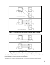
Output Oscillation
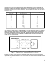
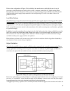
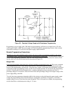
Check for the possibility of power supply oscillation when connected in the system for remote sensing. Figure
52 illustrates that the impedance of the load leads is included inside the power supply feedback loop. In remote
sensing applications involving small or long load wires, there is a tendency for power supply oscillation to
occur due to the phase shift and added time delay associated with the load and sensing leads.
Figure 52. Effect of Load Lead Impedance on Remote Sensing
Removal of such tendency toward oscillation is usually done empirically. In some cases readjusting a "transient
recovery" or "loop stability" control inside the supply will be adequate--in more severe cases the power supply
loop equalization may have to be redesigned and tailored for the application.
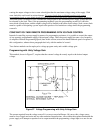
As suggested previously, capacitor Co' is commonly included in order to suppress load transients and reduce the