


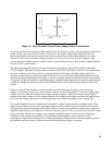
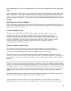
41
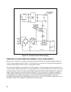
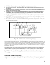
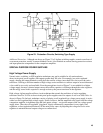
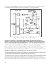
2. The crowbar circuit creates an extra current path during normal operation of the supply, thus changing the
current that flows through the current monitoring resistor. Diode CR1 keeps this extra current at a fixed
level for which compensation can then be made in the constant current comparator circuit.
3. In preregulated supplies the crowbar turns off the preregulator circuit when the SCR fires, reducing the
voltage drop across the series regulator and the current flow through the SCR.
4. An auxiliary winding is included on the blocking oscillator transformer for connection to an additional
crowbar. Tandem crowbar operation is then available for coincident firing of all crowbars in a system.
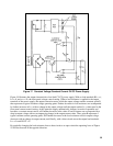
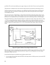
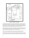
Crowbar Response Time
The crowbar's speed of response to an overload is a critical parameter. If the response time is too slow, the
output could rise to a level high enough to damage the load. If the response is too fast, then spurious noise can
cause false tripping and create a nuisance condition.
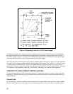
There are three time delays that place a practical limit on how fast crowbars can react. In order of decreasing
magnitude, they are:
(1) The typical SCR turn-on time (from lµsec to around 5µsec);
(2) The reaction time of the trigger circuit; and
(3) The time delay associated with the crowbar voltage-sensing circuit. Since only a fraction of the output
voltage is compared with an internal crowbar reference voltage, the voltage sensing circuit incorporates a
large voltage divider which combines with discrete and stray capacitance in the sensing circuit to form an
RC delay network.
If the output voltage is rising relatively slowly there will be essentially no time delay of types (2) and (3). The
SCR will be triggered within a fraction of a microsecond after the relatively slow-rising output voltage crosses
the trip level, and the only noticeable time delay will be the turn-on time of the SCR. If, on the other hand, the
output voltage waveform approaches a step, the sense circuit will not follow the fast rising wavefront and an
added time delay (type 3) will result. For a step that is only a few millivolts above the trip level, this time delay
can be as much as a few microseconds; but as the magnitude of the step increases, the sense circuit charges
faster and the delay decreases.
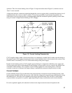
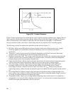
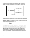
In practice, it is unrealistic to specify either the time delay or the maximum overvoltage as shown in Figure
22A, because they vary according to operating levels, load and line impedances, and the exact failure mode.
Instead Agilent Technologies specifies the overvoltage trip margin, which is defined as "the minimum crowbar
trip setting above the desired operating output voltage to prevent false crowbar tripping".