


74
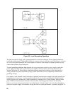
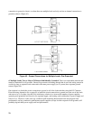
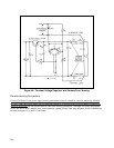
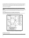
Figure 48. Constant Voltage Regulator with Remote Error Sensing
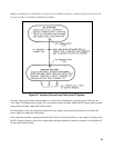
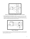
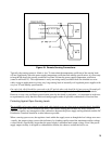
Remote Sensing Connections
Connections between the power supply sensing and output terminals should be removed, and using shielded
two-wire cable, the power supply sensing terminals should be connected to the DC Distribution Terminals as
shown in Figure 49. Do not use the shield as one of the sensing conductors. Although for clarity the diagram
shows the load leads as straight lines, some immunity against pick-up from stray magnetic fields is obtained by
twisting each pair of (+) and (-) load leads.