


88
accuracy will deliver zero volts with zero programming resistance. Thus, the first step in improving the
programming accuracy of Figure 60 is to short the programming terminals and note the output voltage.
Normally, this voltage will be slightly negative. If this is not the case the comparison amplifier packages can
sometimes be interchanged; the output voltage with zero programming resistance will then, in most cases,
become slightly negative. In some supplies, an internal control is provided for adjusting this zero offset voltage.
It is also possible to insert permanently a small resistor in series with the programming leads; this value of
resistance being just sufficient to bring the output voltage up to exactly zero volts.
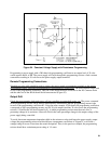
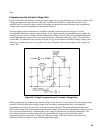
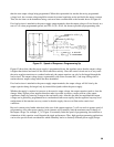
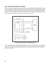
One point of the ideal programming characteristic has now been established. Next, the slope of E
OUT
versus R
P
characteristic must be adjusted so that this straight line will pass through the maximum output voltage with the
proper value of programming resistance. Assume, for example, that we are adjusting a power supply which has
a programming coefficient of 200 ohms per volt and a maximum output voltage of 20 volts. Having inserted
internally a series programming resistance of sufficient value to bring the output voltage to zero volts with zero
ohms external programming resistance, the next step would be to attach a precision 4000 ohm resistor across
the programming terminals and adjust the programming current so that the output voltage would equal 20 volts.
In some supplies this programming current can be adjusted by means of an internal pot. In most cases, however,
it will be necessary to "trim up" a precision resistor (by means of shunt resistors) which determines the
programming current. Having adjusted this constant current, it may be necessary to readjust the zero output
crossing point by shorting the remote programming terminals and trimming the internal programming resistance
(or offset control adjustment) to obtain exactly zero volts.
Once a power supply has its programming characteristic aligned "perfectly" in accordance with the
characteristic shown in Figure 59, this alignment will retain an absolute accuracy within a tolerance found by
adding the power supply specifications for:
a. load regulation
b. line regulation
c. (temperature coefficient) X ( ambient temperature change)
d. drift
Any change in the load resistance, input line voltage, ambient temperature, or warmup time can be expected to
cause slight variations in the output voltage of the supply even though the value of the programming resistance
has not been altered. The capability for remote programming accuracy therefore increases with improvements in
the four specifications mentioned, and high stability power supplies are capable of greater long-term
programming accuracy than standard supplies .
REMOTE PROGRAMMING SPEED
A constant voltage regulated power supply is normally called upon to change its output current rapidly in
response to load resistance changes. In some cases, however, notably in high speed remote programming
applications and constant current applications involving rapidly changing load resistance, the power supply
must change its output voltage rapidly. If the power supply does not employ a preregulator, the most important
factor limiting the speed of output voltage change is the output capacitor and load resistor.
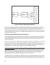
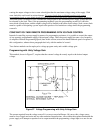
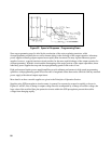
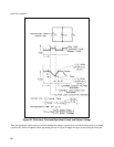
The equivalent circuit and the nature of the output voltage waveform when the supply is being programmed
upward are shown in Figure 61. When the new output is programmed, the power supply regulator circuit senses
that the output is less than desired and turns on the series regulator to its maximum value I
L
, the current limit or
constant current setting. This constant current I
L
charges the output capacitor C
O
and load resistor R
L
in parallel.
The output therefore rises exponentially with a time constant R
L
C
L
toward a voltage level I
L
R
L
, a value higher