


103
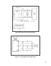
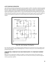
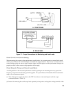
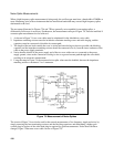
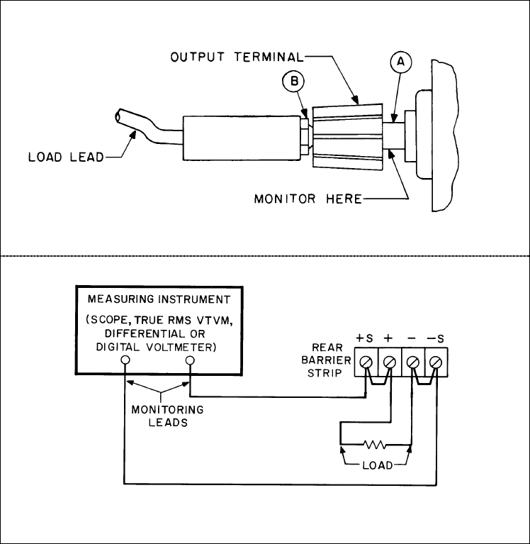
A. FRONT PANEL
B. REAR PANEL
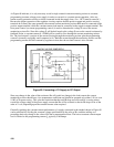
Figure 71. Proper Connections for Monitoring and Load Leads
Check Current Limit Control Setting.
When measuring the constant voltage performance specifications, the constant current or current limit control
must be set well above the maximum output current that the supply will draw. The onset of constant current or
current limiting action can cause a drop in output voltage, increased ripple, and other performance changes not
properly ascribed to the constant voltage operation of the supply.
Check Setup for Pickup and Ground Loop Effects.
Avoid degradation of the measured performance caused by pickup on the measuring leads or by power line
frequency components introduced by ground loop paths. Two quick checks will determine if the measurement
setup is free of extraneous signals:
(a) Turn off the power supply and observe the CRT for evidence of unwanted signals (with the scope
connected between + S and - S).
(b) Instead of connecting the oscilloscope leads separately to the positive and negative sensing terminals of the