


30
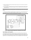
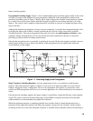
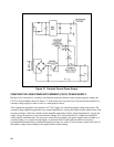
catch diode) was not required in the two transistor regulators of Figures 10 and 11 because of their full-wave
rectifier configuration.
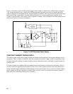
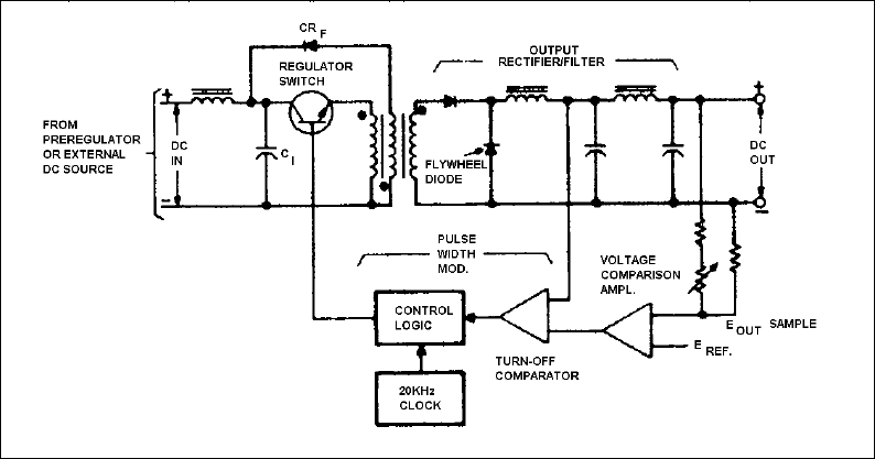
Another item not found in the previous regulators is "flyback" diode CR
F
. This diode is connected to a third
transformer winding which is bifilar wound with the primary. During the off periods of the switch, CR
F
is
forward biased, allowing the return of surplus magnetizing current to the input filter, and thus preventing
saturation of the transformer core. This is an important function because core saturation often leads to the
destruction of switching transistors. In the previously described two transistor push-pull circuits, core saturation
is easier to avoid because magnetizing current is applied to the core in both directions. Nevertheless, matched
switching transistors and balancing capacitors must still be used in these configurations to ensure that core
saturation does not occur.
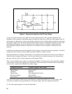
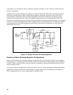
Figure 12. Single Transistor Switching Regulator
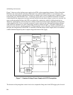
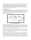
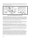
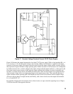
Summary of Basic Switching Regulator Configurations
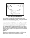
Figure 13 shows three basic switching regulator configurations that are often used in today’s power supplies.
Configuration A is of the push-pull class and this version was used in the switching supplies shown in Figures
10 and 11. Other variations of this circuit are used also, including two-transistor balanced push-pull and four
transistor bridge circuits.
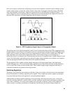
As a group, push-pull configurations are the most effective for low-voltage, high-power and high performance
applications. Push-pull circuits have the advantage of a ripple frequency that is double that of the other two
basic configurations and, of course, output ripple is inherently lower.