


63
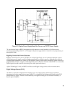
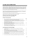
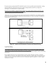
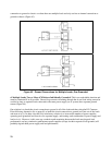
If remote sensing is employed, the DT's should be located as close as possible to the load terminals - sensing
leads should then be connected from the power supply sensing terminals to the DT's (see Figure 36).
(See Figure 47 for further details on remote sensing.)
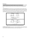
One pair of wires should be connected directly from the power supply output terminals to the DT's, and a
separate pair of leads from the DT's to each load. There should be no direct connection from one load to
another, except by way of the DC Distribution Terminals.
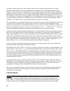
Although for clarity the diagrams show the load and sensing leads as straight lines, some immunity against
pick-up from stray magnetic fields is obtained by twisting each pair of (+) and (-) load leads. In addition all
sensing leads should be shielded.
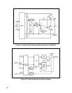
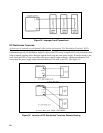
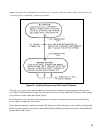
B. WITH MULTIPLE LOAD – USING DT's SEPARATE
FROM POWER SUPPLY AND LOAD TERMINALS.
Figure 36. Location of DC Distribution Terminals with Remote Sensing
Load Wire Rating
As an absolute minimum, each load wire must be of sufficient size to carry the power supply output current
which would flow if the associated load terminals were short circuited. However, impedance and coupling
considerations usually dictate the use of load current wires larger than required simply to satisfy current rating
requirements.
Power supplies and load wires are usually thought of in terms of their schematic equivalents - the battery
symbol and line connections. The simplistic circuit models which these symbols imply are adequate for many
purposes, but more exact models must be used when evaluating the regulation properties of a power supply
connected to its load(s).