


72
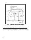
DC Ground Point
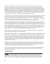
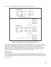
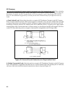
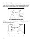
The CP should be connected to the GP as shown in Figures 40 through 43 (unless one load is already
grounded), making certain there is only one conductive path between these two points. This connection should
be such that the total impedance from the DC Common for example, be the separate ground terminal located on
one of the power supplies or loads in a system, or it may be a special system ground terminal, bus, or plane
established expressly for ground connection purposes.
The CP should be connected to the GP as shown in Figure 40 through 43 (unless one load is already
grounded), making certain there is only one conductive path between these two points. This connection should
be such that the total impedance from the DC Common Point to the DC Ground Point is not large compared
with the impedance from the GP to earth ground. Braided leads are sometimes used to further reduce the high
frequency component of this ground load impedance.
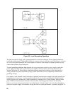
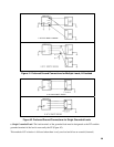
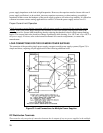
Sometimes the impedance between the CP and the GP is minimized by using a single terminal or bar for both.
In these cases, care should be taken that all DC System connections are made at one end of the terminal or bar,
and any Ground System connection at the other, so that the DC and Ground System currents are not
intertwined.
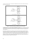
When checking for unintentional paths from dc to ground, be sure that any straps or wires between power
supply output and ground terminals have been removed (unless, of course, this is the single desired connection
between the CP and the GP).
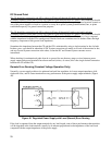
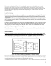
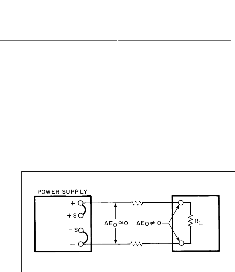
Remote Error Sensing (Constant Voltage Operation Only)
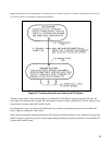
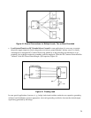
Normally, a power supply achieves its optimum load and line regulation, its lowest output impedance, drift,
ripple and noise, and its fastest transient recovery performance at the power supply output terminals (Figure
46).
Figure 46. Regulated Power Supply with Local (Normal) Error Sensing
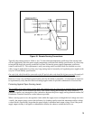
If the load is separated from the output terminals by any lead length, some of these performance characteristics
will be degraded at the load terminals--usually by an amount proportional to the impedance of the load leads
compared with the output impedance of the power supply.