


Chapter 5 Instruction Specifications
5-32
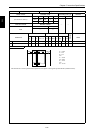
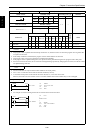
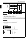
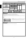
Item number Basic instructions-24 Name Counter (COUNTER)
Ladder format Condition code
Processing time (µs)
Remark
R7F4 R7F3 R7F2 R7F1 R7F0
Average Maximum
DER ERR SD V C
CU n
s
zzzzz
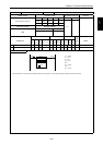
Instruction format Number of steps
1.4
Condition Steps
OUT CU n s — 5
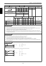
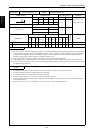
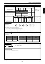
Bit Word Double word
Usable I/O
XY
R,
M
TD, SS,
CU, CT WX WY
WR,
WM TC DX DY
DR,
DM
Constant
Other
n Counter number { 0 to 255 (Decimal)
sSet value {{{ {1 to 65535 (Decimal)
Function
• Increments the progress value by 1 each time the leading edge of the startup condition is detected, and switches on the coil
when the progress value is greater than or equal to the set value. The coil that is switched on turns off when the counter
clear CL n is switched on, and the progress value is cleared to 0.
• The progress value is set in TC n and does not exceed 65535 (decimal).
• If the progress value is updated while the system is running, the operation will be performed using the new progress value at
that point.
• If an I/O is set for the set value, the set value can be changed during operation by changing the I/O value, since the set values
are updated during each scan.
Notes
• A maximum of 256 points can be used for the timers and counters TD, SS, CU, CTU and CTD in total.
• The timer numbers and counter numbers can not be overlapped.
• While the counter clear CL n is on, the rise of startup condition is ignored.
• Since the startup condition of the counter is edge detection, the condition for one scan can not be detected during the first
scan after RUN starts.
• If the set value is set to 0, it is regarded as a coil that is always on and controlled by the CL n.
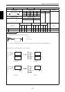
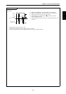
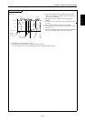
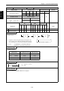
Program example
X00005
CU15
LD X00005
OUT CU15 4
LD X00006
OUT CL15
LD CU15
OUT R105
X00006
CL15
4
CU15
R105
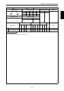
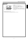
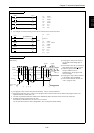
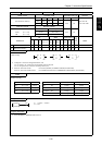
• An example of a word I/O being used as the set value for the circuit shown above.
R7E3
X00005
CU15
WR0015
X00006
CL15
WR0015=4
LD R7E3
[
WR0015=4
]
LD X00005
OUT CU15 WR0015
LD X00006
OUT CL15
LD CU15
OUT R105
CU15
R105
OUT CU n s