


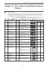

Chapter 12 Error Code List and Special Internal Outputs
12-7
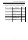
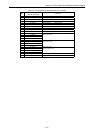
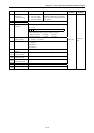
No. Name Meaning Description
Setting
condition
Resetting
condition
R7EB Clear retentive area 1: Clear retentive area
R7EC Clear error code 1: Clear error code in WRF000 to F00A, R7C8 to 7DE
Set by user
Cleared by
the system
R7ED Undefined Do not use.
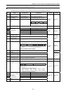
R7EE Battery error
detection
enable/disable
1: Detection enabled
0: Detection disabled
Be sure to set if battery is used.
Set by user
Cleared by
user, or when
retentive area
is cleared, or
the CPU is
initialized.
R7EF Backup memory
writing execution
flag
1: Being written
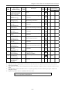
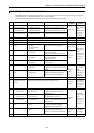
R7F0 Carry flag (CY) 0: No carry
1: Carry
Indicates whether there is a carryover
from the operation result
R7F1 Overflow flag (V) 0: No overflow
1: Overflow
Indicates whether there is overflow in
the operation result
Set by the
system *3
Cleared by
the system
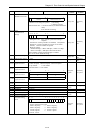
R7F2 Shift data (SD) 0: Shift data “0”
1: Shift data “1”
Designates the shift data used in shift
instructions, etc.
Set by user
Cleared by
user
R7F3 Operation error
(ERR)
0: Normal
1: Error
Indicates whether there is an operation
error when operation is executed
R7F4 Data error (DER) 0: Normal
1: Error
Indicates whether there is a data error
when operation is being executed.
Set by the
system
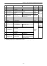
R7F5 Special I/O function
setting flag
1: Request to set For counter, PWM and pulse train
R7F6 Special I/O
parameters to write in
FLASH *4
1: Request to write For counter, PWM and pulse train
Set by user
R7F7 Special I/O parameter
error
0: Normal
1: Error
Indicates the results of the special I/O
parameter settings.
Set by the
system
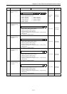
R7F8 Calendar, clock read
request
1: Request to read Read the present values of calendar,
clock and set in WRF01B to WRF01F
R7F9 Calendar, clock
setting request
1: Request to write Set the data set in WRF01B to
WRF01F in the calendar and clock
R7FA
Clock ± 30 second
adjustment request
1: Request adjustment When second data (WRF00F) is 0 to
29, it becomes 0 seconds and when it is
30 to 59, +1 minute is added and
second data becomes 0
Set by user
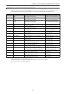
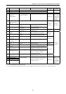
R7FB Calendar and clock
set data error
0: Normal
1: Error
Indicates whether there is an error in
calendar and clock set data
Set by the
system
Cleared by
the system
R7FC Output control 1
R7FD Output control 2
R7FE Output control 3
R7FF Output control 4
0: Output disabled
1: Output enabled
Sets the enabling and disabling when
Y100 through Y103 is used as PWM
output, pulse output, and counter
coincidence output.
Set by user
Cleared by
user
(Cleared by
the system in
case of pulse
output)
*3: Cleared by system even when Set by user.
*4: The word special internal output that can be written using this function is shown in Table 12.1 on the following page.