


Chapter 5 Instruction Specifications
5-112
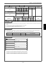
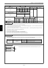
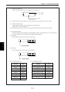
Item number Control instructions-11 Name Start interrupt scan program (INTERRUPT)
Ladder format Condition code
Processing time (µs)
Remark
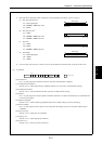
R7F4 R7F3 R7F2 R7F1 R7F0
Average Maximum
INT n DER ERR SD V C
zzzzz
Instruction format Number of steps
0.5
Condition Steps
INT n 1
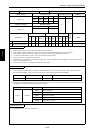
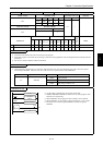
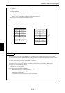
Bit Word Double word
Usable I/O
XY
R,
M
TD, SS,
CU, CT WX WY
WR,
WM TC DX DY
DR,
DM
Constant
Other
n Interrupt priority
{
0 to 2 , 16 to 19, 20
to 27 (Decimal)
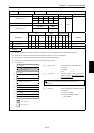
Function
• This instruction declares the start of an interrupt scan program.
• n = 0 to 2 indicates a periodical interrupt scan. n = 16 to 19 indicates interrupt input. n = 20 to 27 indicates an interrupt scan
when the counter input exceeds the preset value.
• It is set to the 10 ms periodic scan when n = 0, 20 ms periodic scan when n = 1, and 40 ms periodic interrupt scan when n =
2.
• The smaller the number n, the higher the interrupt priority.
• Always use INT n and RTI in pairs.
• Even if a startup condition is used for INT n, it will be ignored.
• Code the INT n to RTI subroutine program after the END instruction.
• The n in INT n cannot be used more than once within the same program.
Notes
• This instruction is checked prior to execution, and when there is an error, the following error code is set in the special
internal output WRF001. Also, the CPU error code '34' is set to special internal output WRF000.
CPU error code Special internal output Error code Error description
34 WRF001 H0005 Duplicate definition of INT
H0014 INT undefined
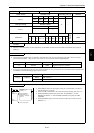
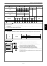
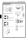
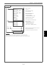
Instruction for use
END
INT 0
RTI
INT 0
scan
10 ms interrupt scan program
• The program between INT0 and RTI is started and executed every 10 ms.
INT n