


Chapter 5 Instruction Specifications
5-140
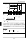
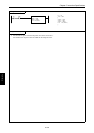
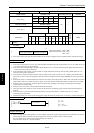
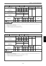
Item number FUN instructions-14 Name Pulse output control
Ladder format Condition code
Processing time (µs)
Remark
R7F4 R7F3 R7F2 R7F1 R7F0
Average Maximum
FUN 149 (s) DER ERR SD V C
↕
zzzz
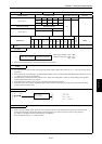
Instruction format Number of steps
149
Condition Steps
FUN 149 (s) — 3
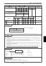
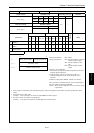
Bit Word Double word
Usable I/O
XY
R,
M
TD, SS,
CU, CT WX WY
WR,
WM TC DX DY
DR,
DM
Constant
Other
s
Argument (Pulse output
number)
{
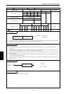
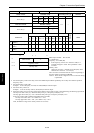
Function
Pulse output number: H01 to H04
Operation instruction: H00 – Stop,
H01 - Start
• Starts pulse output of the specified pulse number and the output is stopped once the specified number of pulses are output.
Notes
• If the pulse output number is set to a value other than H01 to H04 and the pulse output number is set to “0,” DER will be set
to “1”and no processing will be performed.
• If the external I/O corresponding to the pulse output number is set to a function other than pulse output, DER will be set to
“1”and no processing will be performed.
• If the specified counter number is unable to make an output (PI/O function setting result by R7F5), DER will be set to “1”
and no processing will be performed.
• The pulse that is output with this instruction will be a pulse having a duty of 30 to 50 %. (To output a pulse having a duty
ratio of 50 %, set the value corresponding to the CPU model in the special internal output WRF06B, by referring to Section
8.1.4.)
• When pulse output is commenced with this instruction, the output control flag (R7FC to R7FF) that corresponds to the pulse
output number will turn on while the pulse is output. It will turn off when the specified number of pulses have been output.
• When the CPU is not operating, the pulse output continues/stops according to the setting of the special internal output
(output selection at R7DC stop).
• This instruction does not have an acceleration/deceleration function.
• Only pulse output stop operation can be executed for the I/O that is outputting a pulse with the acceleration/deceleration
function.
• If this instruction is executed while the backup memory is being written (R7EF=1), DER will be set to “1” and no
processing will be performed.
• The backup memory will not be written during pulse output. Be extremely careful when you change a program during RUN.
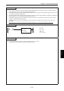
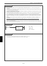
Program example
R9
LD R9
AND DIF9
[
WR9 = H101
FUN 149 ( WR9 )
]
DIF9
WR9 = H0101
FUN 149 (WR9)
Program description
• Prior to starting a pulse output operation, various settings required for the pulse output operation are reflected in the special
internal outputs, and the PI/O function setting flag (R7F5) is turned on while the CPU is being stopped.
For more details on the special internal output settings, see Chapter 8.
Starts the pulse output No. 1 (Y100) operation.
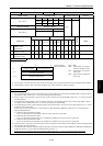
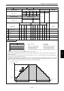
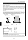
S
15 0
Pulse output number Operation instruction
FUN 149 (s)