


Chapter 4 Product lineup and wiring
4-6
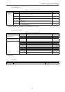
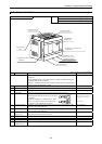
4.5 Expansion Unit
Name and function of each part
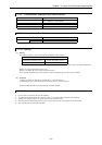
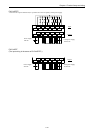
Type EH-*14ED** (same dimension as 14 pts. basic unit)
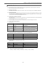
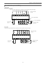
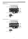
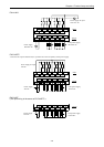
EH-*28ED** (same dimension as 28 pts. basic unit)
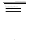
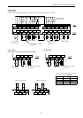
EH-*6EAN (same dimension as 14 pts. basic unit)
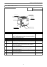
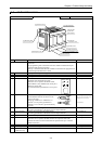
1] POW LED
2] OK LED
3] Expansion connector cover
(left side)
9] Terminal cover
10] Mounting
hole
4] Input terminals
7] Expansion connector cover
(right side)
8] Dummy cover
5] Output terminals
11] DIN rail installation clip
6] Power terminal
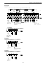
Above picture is 14 points module
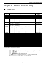
No. Item Detailed explanation Remarks
Explanation of operation Operations are performed according to the contents of the program created
by the user.
The programming unit connected to the CPU module communication port
writes and reads the user program.
Memory is installed inside the CPU module in which the user program and
internal output information are stored.
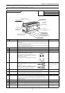
1] POW LED Lighting when the power is supplied.
2] OK LED Lighting at normal operation.
3] Expansion cover
(Left side)
Cover for expansion connector
Used when connecting to the expansion cable from the front unit.
See Chapter 10.
4] Input terminals Terminals for wiring the external input units.
Recommended terminals are shown in the figure
to the right.
One piece of AWG14 to AWG22 (2.1 to 0.36
mm
2
) or two pieces of AWG16 to AWG22 (1.3
to 0.36 mm
2
) per terminal may be wired.
See Chapter 10.
(Make sure that the terminals will not
disengage due to loose screws.)
(Recommended)
5] Output terminals Terminals for connecting the external load. The wiring specification is the
same as for the input terminals.
See Chapter 10.
6] Power terminal Terminal for connecting the power supply. The wiring specification is the
same as for the input terminals.
See Chapter 10.
7] Expansion cover
(Right side)
Cover for expansion connector
Used when connecting to the next unit.
See Chapter 10.
8] Dummy cover Cover used as a dummy.
9] Terminal cover Cover for terminals
10] Mounting hole Used when installing the PLC with screws See Chapter 10.
11] DIN rail
installation clip
Used when installing the PLC on a DIN rail See Chapter 10.
6
6