


Chapter 8 High-speed counter, PWM / Pulse train output and Analogue I/O
8-6
8.2 High-Speed Counter (Single-Phase)
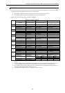
The high-speed counter settings are stored in the special internal outputs (WRF070 to 7E). It is only possible to perform
the setting through the special internal output (WRF071) when the CPU is stopped and the output is turned off. Once all
the input/output settings are completed, the settings of each counter can be changed using the special internal outputs for
individual setting (WRF058 to 5B), regardless of whether the CPU is operating or stopped. In addition, the settings can
be changed by a program using the FUN instruction (FUN140 to 142, and 146). Refer to the chapter about the FUN
instruction for information about how to use the FUN instruction for setting.
8.2.1 Operation of Single-Phase Counter
(1) Basic operation
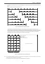
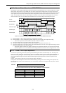
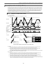
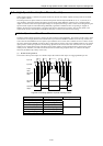
Figure 8.5 describes the basic operation of the high-speed counter.
FFFFH
0000H
U
D
U
D
DUUD
7]
5]
4]
1]
2]
3]
6]
ON
OFF
1]
2]
4]
5]
ON
OFF
ON
INT2mINT2mINT2m INT2nINT2nINT2nINT2nINT2nINT2nINT2mINT2n
OFF
U: Up counter
D: Down counter
On preset
Off preset
Coincidence
output
Coincidence interrupt
occurrence
Coincidence output On
Off preset
Coincidence interrupt
occurrence
Coincidence output On
R7FC to R7FF
n: Even number
m: Odd number
Coincidence
interrupt
On preset
Coincidence interrupt
occurrence
Coincidence output Off
Coincidence interrupt
occurrence
Coincidence output Off
Each coincidence interrupt
and INT number
At on-preset INT20Counter 1
At off-preset INT21
At on-preset INT22Counter 2
At off-preset INT23
At on-preset INT24Counter 3
At off-preset INT25
At on-preset INT26Counter 4
At off-preset INT27
On preset
Off preset
Figure 8.5 Basic operation of high-speed counter (single-phase)
Up counter
1] The counter output turns on* when the current counter value becomes larger than the on-preset value. The
interrupt process (INT2n) starts up if an interrupt program is used in the running user program.
2] The counter output turns off when the current counter value becomes larger than the off-preset value. The
interrupt process (INT2m) starts up if an interrupt program is used in the running user program.
3] The counter values wrap around in a ring. That is, the current counter value goes back to 0h when one more pulse
is counted after the maximum value (FFFFH) is reached.
Down counter
4] The counter output turns on* when the current counter value becomes smaller than the off-preset value. The
interrupt process (INT2m) starts up if an interrupt program is used in the running user program.
5] The counter output turns off when the current counter value becomes smaller than the on-preset value. The
interrupt process (INT2n) starts up if an interrupt program is used in the running user program.
6] The counter values wrap around in a ring. That is, the current counter value becomes FFFFH when one more
pulse is counted after the minimum value (0H) is reached. Note also that the initial value of the counter is 0H, and
the value reaches FFFFH after the first pulse is counted after the start of operation.