


Chapter 8 High-speed counter, PWM / Pulse train output and Analogue I/O
8-9
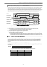
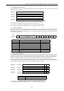
(4) Setting the counter preload
When preloading is used, the value to be preloaded should be set for each counter used. Any value in the range from 0 to
FFFFH (0 to 65,535) can be set.
WRF07A:
Preload value for counter 1
WRF07B:
Preload value for counter 2
WRF07C:
Preload value for counter 3
WRF07D:
Preload value for counter 4
Figure 8.11 Special internal outputs for setting the preload values
This special internal output becomes valid immediately after the setting.
In case of mode 1, WRF07C and WRF07D are used to set the number of pulse outputs.
In case of mode 4, WRF07B and WRF07B are used to set the number of pulse outputs.
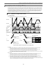
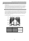
(5) At abnormal setting
If the on-preset and off-preset settings contain the same values for one or more counters when the PI/O function setting
flag (R7F5) is turned on, the corresponding bit in the error display special internal output turns on and the counters with
error settings do not perform any counting. (It does not count even if a counter input is entered.) In addition, the setting
abnormal flag (R7F7) turns on.
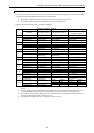
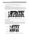
Bit:
1514131211109876543210
WRF057:
a Not used bcdefghi
Figure 8.12 Special internal output for setting error display
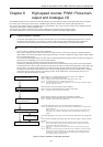
Bit Description of abnormality Related terminal
a Total pulse frequency abnormality Y100 to Y103
b Pulse 4 frequency abnormality Y103
c Pulse 3 frequency abnormality Y102
d Pulse 2 frequency abnormality Y101
e Pulse 1 frequency abnormality Y100
f Counter 4 preset value abnormality X6
g Counter 3 preset value abnormality X4
h Counter 2 preset value abnormality X2
i Counter 1 preset value abnormality X0
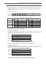
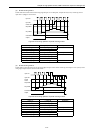
(6) Individual counter setting
The on-preset and off-preset values can be changed for each counter by the special internal outputs for individual setting
regardless of whether the CPU is operating or stopped. Turn on the corresponding bit in the following special internal
outputs when only the on-preset or the off-preset value should be changed for a certain counter input. (To change both
settings at the same time, set the “H3” in the corresponding special internal outputs for individual setting.)
Moreover, when the specified on-preset and off-preset values are the same, the corresponding bit of the error display
special internal output is turned on and operation is performed using the preset value before the setting. (The set value for
the special internal output also returns to the preset value before the setting was made)
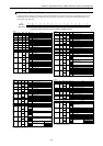
15 2 1 0
WRF058: Counter 1
Not used a b
WRF059: Counter 2
Not used a b
WRF05A: Counter 3
Not used a b
WRF05B: Counter 4
Not used a b
Figure 8.13 Special internal outputs for individual counter setting
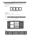
Bit Description
a Off-preset change request
b On-preset change request
In case of mode 1, WRF05A and WRF05B are used to set individual PWM/pulse outputs.
In case of mode 4, WRF059 and WRF05A are used to set individual PWM/pulse outputs.