


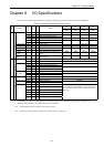

Chapter 6 I/O Specifications
6-1
Chapter 6 I/O Specifications
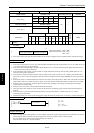
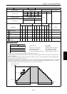
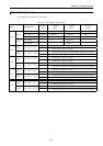
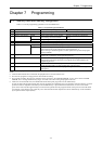
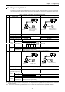
Table 6.1 lists the input/output classifications and input/output point types that can be used with the MICRO-EH
Table 6.1 Usable I/O classifications and point types
10-point
type
14-point
type
23-point
type
28-point
type
Item
Function
Symbol
Size
10/16
Name
Number of
points
Number of
points
Number of
points
Number of
points
1 External I/O X B 10 Bit external input 6 points 8 points 13 points 16 points
WX W 16 Word external input 1 word 1 word 1 word 2 words
DX D 16 Double-word external input
Y B 10 Bit external output 4 points 6 points 10 points 12 points
WY W 16 Word external output 1 word 1 word 1 word 1 word
DY D 16 Double-word external output
Analog input WX W 16 Analog input - - 2 words -
Analog output WY W 16 Analog output - - 1 word -
Counter input X B 10 High-speed counter input 3 points 4 points 4 points 4 points
Interrupt input X B 10 Interrupt input total total total total
Counter
output
Y B 10 High-speed counter synchronized
output
3 points 4 points 4 points 4 points
External I/O*
Pulse/PWM
output
Y B 10 Pulse output
PWM output
3 point 4 points 4 point 4 points
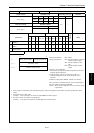
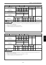
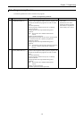
2 Bit R B 16 Bit internal output 1984 points
R B 16 Bit special internal output 64 points
Word WR W 16 Word internal output 4096 words
DR D 16 Double-word internal output
WR W 16 Word special internal output 512 words
DR D 16 D.-word special internal output
Sharing of M B 16 Bit internal output 16384 points
bit / word WM W 16 Word internal output 1024 words
Internal I/O
DM D 16 Double-word internal output
3 Edge detection DIF B 10 Rising edge 512 points
DFN B 10 Falling edge 512 points
Master control MCS B 10 Master control set 50 points
MCR B 10 Master control reset
Timer counter
TD
B 10 On delay timer
SS
B 10 Single-shot timer
CU
B 10 Up counter
CTU
B 10 Up-down counter up input
CTD
B 10 Up-down counter down input
Others
CL
B 10 Clear progress value
Timer 256 points (0.01 s timer has only 0 to 63)
Counter 256 points (The same area as the timer is used.)
(The same timer counter number cannot be used more
than once.)
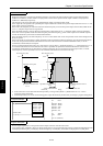
*: The external I/O, counter I/O, interrupt input, pulse/PWM outputs use the same area by specifying the operation I/O
operation mode (WRF070). See Chapter 8 for further information.
Note: The MICRO-EH does not support CPU link area (L/WL).
Note: B and W in the Size column represent bit and word (16 bits), respectively.