


Chapter 11 Communication Specifications
11-2
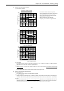
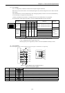
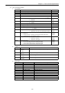
(1) Port 1 settings
Port 1 is configured by combination of DIP switch and special register (WRF01A).
DIP switch can be set when cable is not connected (DR signal is off). Switch configuration is set at cable connected
(DR is high).
Value in WRF01A is saved in FLASH memory when writing flag (R7F6) is turned on. If saved in FLASH memory,
it is not necessary to set again at the next power up.
[ Caution ] If transmission procedure 2 is configured and saved in FLASH memory once, peripheral
device/application which supports procedure 1 such as LADDER EDITOR can not be connected.
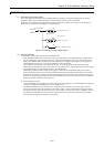
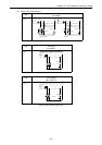
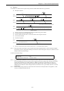
DIP switch
Port type
1234
WRF01A Remarks
38.4 kbps ON off ON off
19.2 kbps ON off off off
9600 bps off off ON off
Dedicated
port
4800 bps off off off off
H0000 : Transmission procedure 1
H8000 : Transmission procedure 2
Default
4800 bps H0000 : Prcd. 1 / H8000 : Prcd. 2
9600 bps H0100 : Prcd. 1 / H8100 : Prcd. 2
19.2 k bps H0200 : Prcd. 1 / H8200 : Prcd. 2
38.4 k bps H0300 : Prcd. 1 / H8300 : Prcd. 2
57.6 k bps H0400 : Prcd. 1 / H8400 : Prcd. 2
Dedicated
port via
modem
2400 bps
off ON off off
H0500 : Prcd. 1 / H8500 : Prcd. 2
H0*** :
Procedure 1
H8*** :
Procedure 2
General purpose port Port switching by FUN5 command, Baud rate by TRNS/RECV command
* Due to no DIP switch equipped, 10 points type does not support modem function.
* +12V is supplied from pin 4 if DIP switch is ON.
* General purpose port is supported by software version 0130 (WRF051=H0130) or newer.
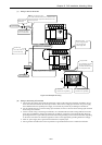
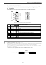
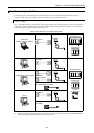
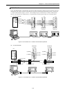
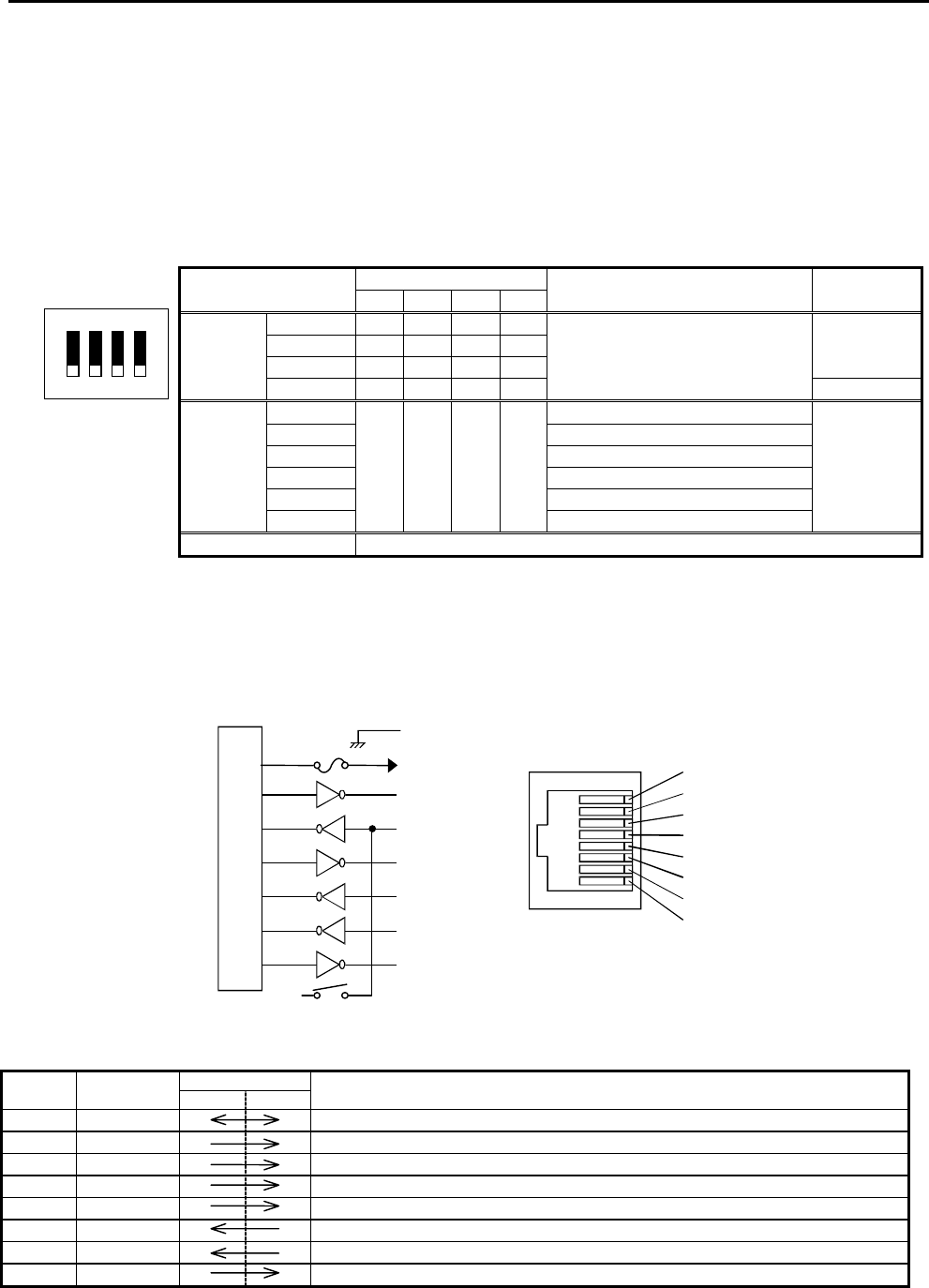
(2) Port 1 hardware
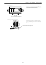
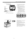
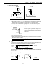
The circuit diagram of port 1 and the signal list are shown in Figure 11.2 and Table 11.3 respectively.
Figure 11.2 Circuit diagram and pin numbers for port 1
Table 11.3 List of port 1 signals
Pin No. Signal Direction Meaning
abbreviation CPU Host
1] SG1 Signal ground
2] VCC 5 V DC is supplied. (Protective fuse is connected.)
3] DTR1 (ER) Communication enabled signal. When it is high, communication is possible.
4] CD1 (DCD) 12V is output when DIP switch 1 is on.
5] SD1 (TXD) Data sent by the CPU
6] RD1 (RXD) Data received by the CPU
7] DR1 (DSR) Peripheral units connected signal. When it is high, peripheral device is connected.
8] RS1 (RTS) Transmission request signal. When it is high, CPU is ready to receive data.
TX1
RX1
DR1
RS1
1] SG1
2] VCC
3] DTR1
4] CD1
5] SD1
6] RD1
7] DR1
8] RS1
12 V
5 V
ER1
DCD1
Micro processor
1]
2]
3]
4]
5]
6]
7]
8]
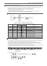
4321
ON