Chapter 5 Instruction Specifications
5-22
Item number Basic instructions-13, 14 Name Set (start)/reset (cancel) master control (MCS, MCR)
Ladder format Condition code
Processing time (µs)
Remark
R7F4 R7F3 R7F2 R7F1 R7F0
Average Maximum
DER ERR SD V C Upper case: MCS
MCS n
MCR n
S
R
MCS n
MCR n
zzzzz 0.7
←
Lower case: MCR
Instruction format Number of steps
MCS n
Condition Steps
MCR n MCS n 3 0.7
←
MCR n 2
Bit Word Double word
Usable I/O
XY
R,
M
TD, SS,
CU, CT WX WY
WR,
WM TC DX DY
DR,
DL,
DM
Constant
Other
n Number { 0 to 49 (Decimal)
Function
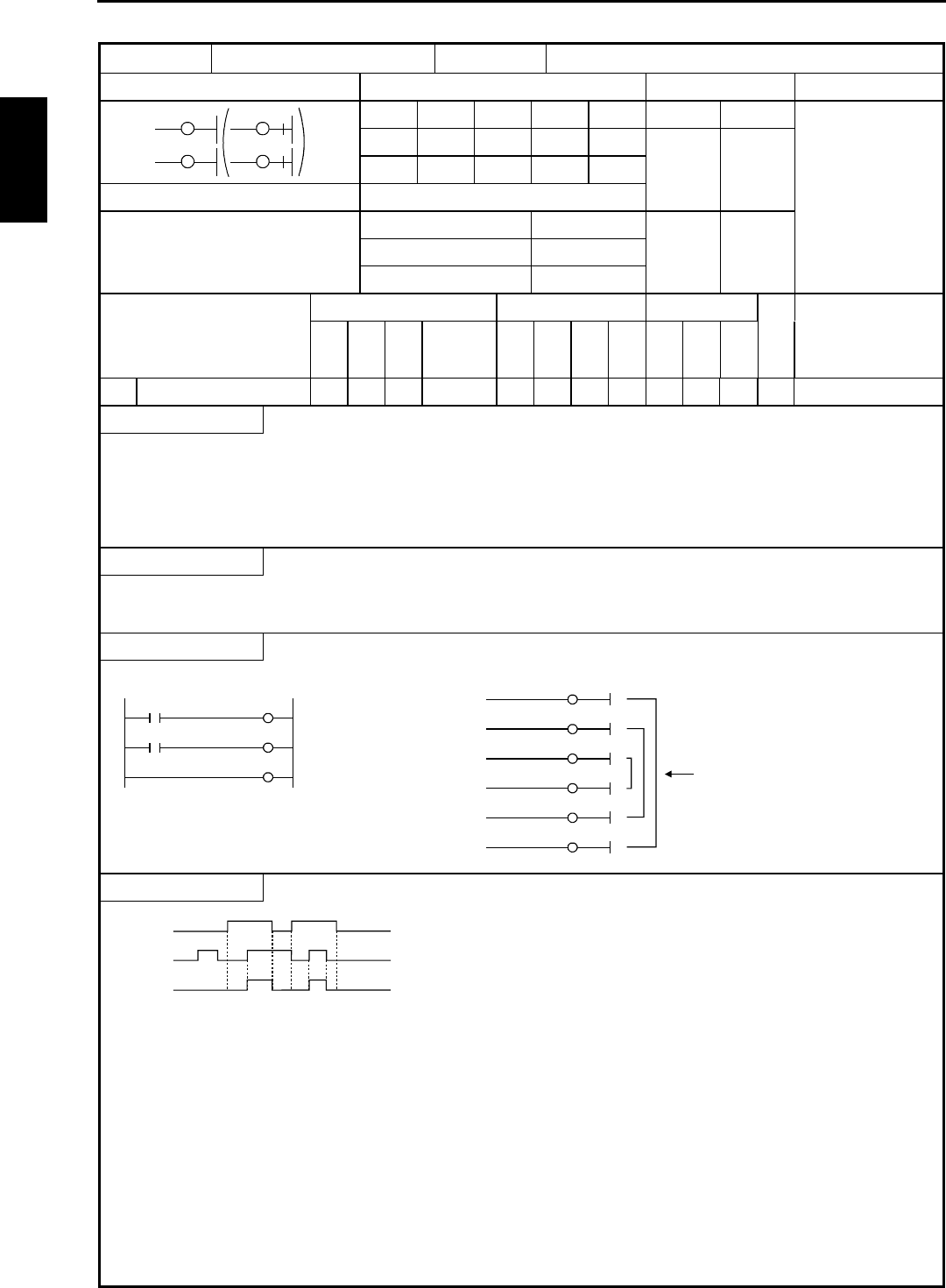
• Controls the input to the circuit sandwiched by the master control set (MCS n) and reset (MCR n).
(An AND operation is performed with respect to each input and MCS.)
• The master control can be used up to eight layers.
( ) indicates the display when the Ladder Editor is used.
Notes
• Always use the master control MCS and MCR in pairs.
Program example
X00000
X00001
MCS1
Y00100
MCR1
LD X00000
MCS1
LD X00001
OUT Y00100
MCR1
MCS0
MCS1
MCS2
MCR2
MCR1
MCR0
Up to eight layers
are allowed.
Program description
X
00000
X
00001
Y
00100
• When input X00000 is on, the circuits surrounded by MCS and MCR obeys input X00001, and output Y00100 turns on/off.
• When input X00000 is off, the circuits surrounded by MCS and MCR are independent of input X00001, and output Y00100
turns off.
MCS n
MCR n


