


Chapter 8 High-speed counter, PWM / Pulse train output and Analogue I/O
8-10
8.3 High-Speed Counter (Two-Phase Counter)
When operation mode 3 is selected, two-phase counters can be used. Four kinds of phase counting modes are available
for two-phase counters.
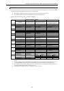
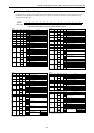
The settings of the two-phase counters are stored in the special internal outputs (WRF06F to 72, 76, 7A, and 7E). It is
only possible to perform the settings through the special internal output (WRF071) when the CPU is stopped and the
output is turned off. Once all the input/output settings are completed, the setting of each counter can be changed using the
special internal outputs for individual setting (WRF058), regardless of whether the CPU is operating or stopped. In
addition, the setting can be changed by a program using the FUN instruction (FUN140 to 142, and 146). Refer to the
chapter about the FUN instruction for information about how to use the FUN instruction for setting.
8.3.1 Operation of Two-Phase Counters
The phase counting mode settings are stored in the special internal output (WRF06F). The operation of the counter values
is the same as for a single-phase counter and likewise wrap around from 0000H to FFFFH. In case of an up counter, the
count value becomes 0000H if one more pulse is input while the current count value is FFFFH. In case of a down counter,
the count value becomes FFFFH if one more pulse is input while the current count value is 0000H. Moreover, the preload
input operation, strobe input operation, and executing operation of the current value clear instruction are run in the same
manner as for a single-phase counter. The status of the counter output is stored in the data memory at the timing of the
refresh process. Therefore, it should be noted that the status monitored by peripheral units, etc. and the actual output
status may be different (by a delay of one scan).
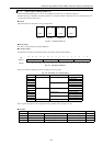
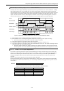
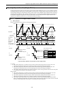
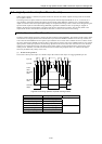
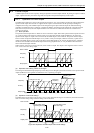
(1) Phase counting mode 0
The counter counts up when input 1A is ahead of input 1B, and down when input 1A is lagging behind input 1B.
Figure 8.14 Counting operation of phase counting mode 0
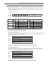
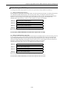
Input 1A Input 1B Operation
1 (High)
↑ (Rising edge)
Up count
0 (Low)
↓ (Falling edge)
↓ (Falling edge)
1 (High)
↑ (Rising edge)
0 (Low)
0 (Low)
↑ (Rising edge)
Down count
1 (High)
↓ (Falling edge)
↓ (Falling edge)
0 (Low)
↑ (Rising edge)
1 (High)
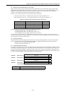
Coincidence
output
On preset
value
Off preset
value
Count
value
Input 1B
Input 1A