


Chapter 10 PLC Installation, Mounting, Wiring
10-1
Chapter 10 PLC Installation, Mounting, Wiring
10.1 Installation
(1) Installation location and environment
(a) When installing the MICRO-EH, use the unit under the environment within the general specification.
(b) Mount the PLC onto a metal plate.
(c) Install the PLC in a suitable enclosure such as a cabinet that opens with a key, tool, etc.
(2) Installing the unit
(a) Precautions when installing the unit
1] When installing the base unit, fix it securely with screws in 2 places (M4, length 20 mm or more) or DIN
rail.
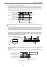
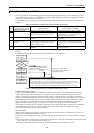
2] To use the unit within the ambient temperature range,
a) Allow ample space for air circulation. (50 mm or more at top and bottom, 10 mm or more to the left
and right)
b) Avoid installing the unit directly above equipment that generates significant heat (heater, transformer,
large-capacity resistance, etc.)
c) When the ambient temperature reaches more than 55 °C, install a fan or cooler to lower the
temperature to below 55 °C.
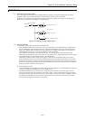
3] Avoid mounting inside a panel where high-voltage equipment is installed.
4] Install 200 mm or more away from high-voltage lines or power lines.
5] Avoid upside down, vertical or horizontal mounting.
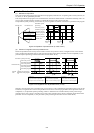
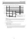
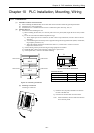
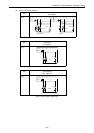
L2
L1
Figure 10.2 External dimensions
Dimensional table
Unit L1 L2
10-point 65 70
14-point (basic, exp.) 85 80
23, 28-point (basic, exp.) 140 80
Unit: mm
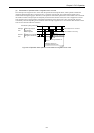
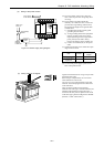
(b) Mounting to a DIN rail
Attaching to a DIN rail
1] Hook the claw (top side) attached to the back of
the unit to the DIN rail.
2] Press the unit into the DIN rail until it clicks.
Note: After installation, check to make sure the base
unit is securely fixed.
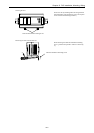
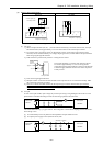
Figure 10.1 Mounting clearances
P L C
P L C
10 mm or more
50 mm or more
Wiring duct
10 mm or more
10 mm or more
10 mm or more
50 mm or more
50 mm or more
50 mm or more
2]
1]