


Chapter 4 Product lineup and wiring
4-5
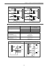
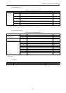
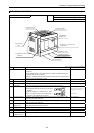
4.4 23-Point and 28-Point Basic Unit
Name and function of each part
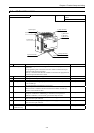
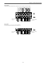
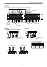
EH-*23***
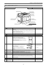
EH-*28***
Type
1] POW LED
2] OK LED
3] RUN LED
10] Terminal cover
13] RS-485 port cover
11] Mounting
hole
4] Serial port cover
5] Input terminals
8] Expansion
connector cover
9] DIP SW cover
6] Output terminals
12] DIN rail installation clip
7] Power terminal
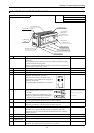
No. Item Detailed explanation Remarks
Explanation of operation Operations are performed according to the contents of the program created
by the user.
The programming unit connected to the CPU module communication port
writes and reads the user programs.
Memory is installed inside the CPU module in which the user programs and
internal output information are stored.
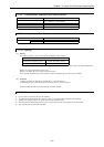
1] POW LED Lighting when the power is supplied.
2] OK LED Lighting at normal operation. See Chapter 12.
3] RUN LED Lighting at RUN status.
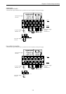
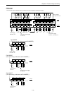
4] Serial port cover Cover for the connector for connecting
peripheral units and the RUN switch.
When the cover is opened, the RUN switch,
potentiometers (VR), and RS-232C serial port 1
(PORT 1) can be used.
The communication specification is set to port 1.
See Chapters 8 and 11.
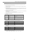
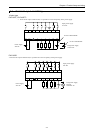
5] Input terminals Terminals for wiring the external input units.
Recommended terminals are shown in the figure
to the right.
One piece of AWG14 to AWG22 (2.1 to 0.36
mm
2
) or two pieces of AWG16 to AWG22 (1.3
to 0.36 mm
2
) per terminal may be wired.
See Chapter 10.
(Make sure that the terminals will not
disengage due to loose screws.)
(Recommended)
6] Output terminals Terminals for connecting the external load.
The wiring specification is the same as for the input terminals.
See Chapter 10.
7] Power terminal Terminal for connecting the power supply.
The wiring specification is the same as for the input terminals.
See Chapter 10.
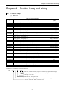
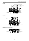
8] Expansion cover Cover for the expansion connector See Chapter 10.
9] DIP SW cover Cover for the DIP switches and the backup battery storage unit.
When the cover is opened, the DIP switches are exposed. These DIP
switches are used to set the communication speed of serial port 1 and the
modem connection.
See Chapter 11.
10] Terminal cover Cover for terminals
11] Mounting hole Used when installing the PLC with screws See Chapter 10.
12] DIN rail
installation clip
Used when installing the PLC on a DIN rail See Chapter 10.
13] RS-485 port cover Cover for RS-485 port. It is connected with a D sub 15-pin female
connector. The communication specification is set to port 2.
See Chapter 11.
STOP
RUN
VR1 VR2
PORT1
6
6