


Chapter 5 Instruction Specifications
5-20
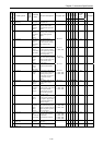
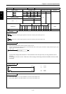
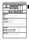
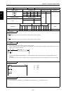
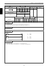
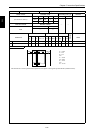
Item number Basic instructions-10 Name Coil output (OUT)
Ladder format Condition code
Processing time (µs)
Remark
R7F4 R7F3 R7F2 R7F1 R7F0
Average Maximum
DER ERR SD V C
zzzzz
Instruction format Number of steps
1.0
←
Condition Steps
OUT n
1
Bit Word Double word
Usable I/O
XY
R,
M
TD, SS,
CU, CT WX WY
WR,
WM TC DX DY
DR,
DM
Constant
Other
n I/O number {{ {
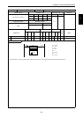
Function
• Switches on the coil when the operation result obtained up to that point is “1.”
• Switches off the coil when the operation result obtained up to that point is “0.”
Notes
• L becomes the internal output when link modules are not used.
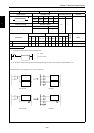
Program example
X00000
X00001
Y00100
Y00101
LD
OUT
LD
OUT
OUT
X00000
Y00100
X00001
Y00101
Y00102
Y00102
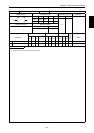
Program description
• When input X00000 is on, the operation is “1” and Y00100 turns on.
• When input X00001 is on, the operation is “1,” and Y00101 and Y00102 turn on.
n
OUT n