


Chapter 11 Communication Specifications
11-5
11.5 Modem Control Function
The 14-point or higher MICRO-EH is equipped with a modem control function. The modem control function can be
operated using task codes. To use this function, it is necessary to set No.2 of the DIP SW.
For details on the communication specifications, see Table 11.1, “Specifications of port 1.”
* The 10-point type CPU does not have this function.
Connecting two operating modems may be difficult if there is a significant difference between them in terms of
communication speeds. Thus, use the models having the same communication speed.
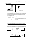
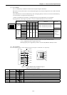
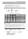
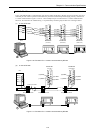
11.5.1 Configuration
Figure 11.5 Modem connection configuration diagram
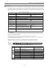
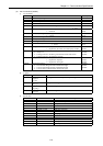
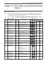
Table 11.7 List of port 1 signals when a modem is connected
Pin No. Signal Direction
abbreviation CPU Host
Meaning
1] SG1 Signal ground
2] CD1 Carrier receive in-progress notification signal
Connected to CD in the modem.
3] ER1 Communication enabled signal of the terminal
4] ER2 Not used
5] SD1 Data sent by the CPU
Connected to SD in the modem.
6] RD1 Data received by the CPU
Connected to RD in the modem.
7] DR1 Communication enabled signal of the modem
Connected to DR in the modem.
8] RS1 Transmission request signal
Connected to RS in the modem.
11.5.2 AT Commands
The AT commands are used to make various modem settings, and are set from the host computer. The MICRO-EH issues
the AT commands automatically for initial setting. Other than this, the AT commands are not used.
Refer to instruction manual or other documents furnished by modem manufacturers for details on the AT commands.
In AT commands, an instruction sent to the modem from the host is called a “command,” and the character string in
response to the “command” returned to the host from the modem is called a “result code.”
AT commands always begin with the character string “AT,” and a return code is input at the end of the command. However,
A/ is excluded. The command that follows the “AT” can have multiple inputs in a single line.
Example)
AT&C1&S0P2CRLF
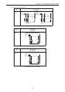
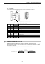
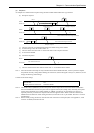
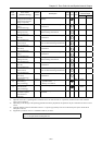
(1) Format
1] AT command format
LFCRAT
command parameter command parameter · · · ·
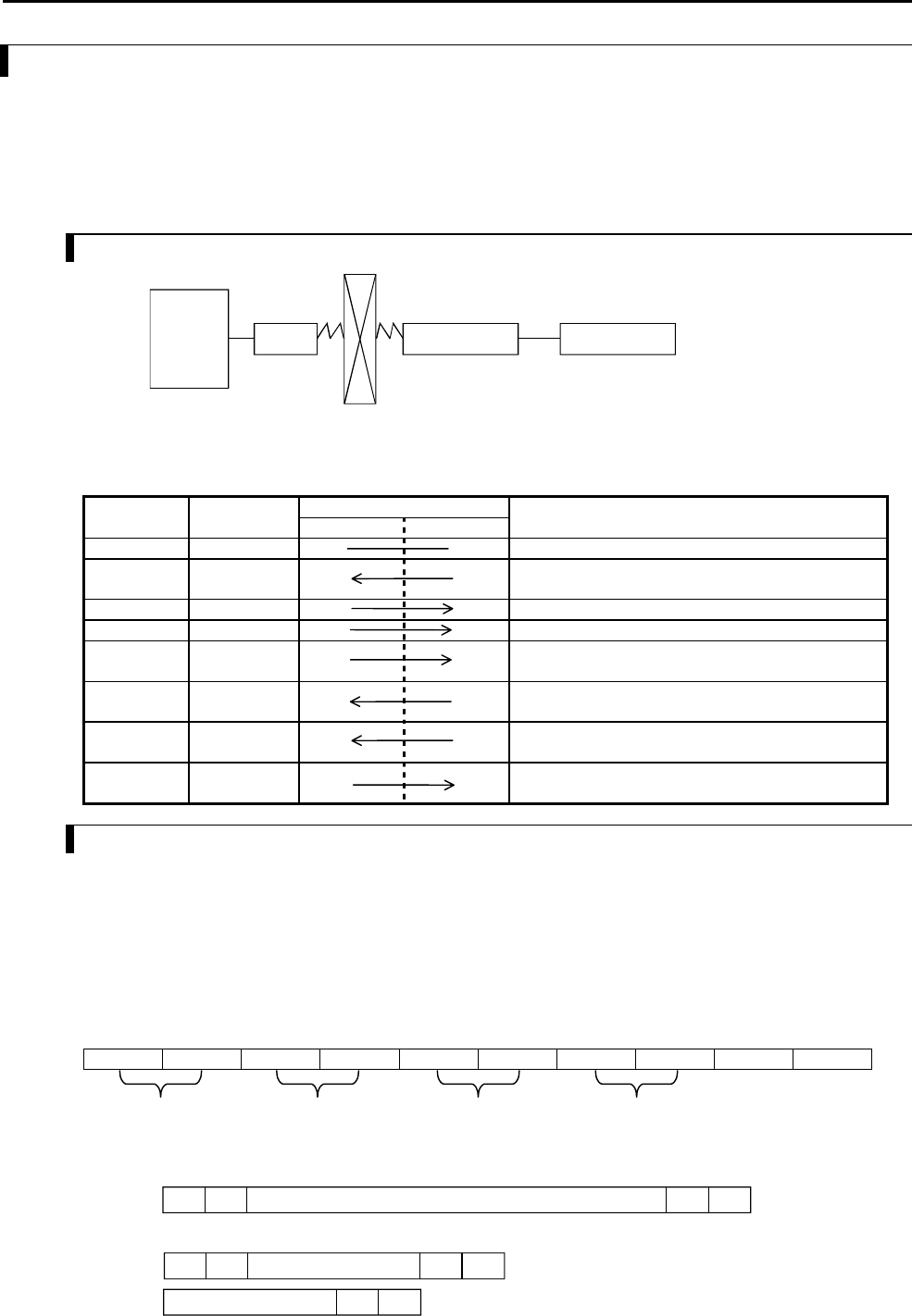
2] Result code format
CR LF CR LF
CR LF
Result code (word)
Result code (number)
AT commands CD signals: Follows the
carrier signals generated
by the opposite device
DR signals: Always On
20 pps (pulse setting)
MICRO-EH
RS-232C
(MAX 57.6 kbps)
Personal
computer
Modem Modem
Public line