


Chapter 11 Communication Specifications
11-7
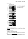
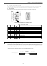
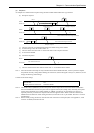
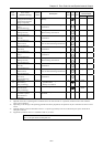
(3) Sequence
An example of a communication sequence using the Omron-made modem ME3314A is given below.
(a) Reception sequence
MICRO-EH
MICRO-EH
MICRO-EH
ATE0Q0V0&C1&S0 CR LF
0CR
2CR
3]
2CR2CR
1CR
ATA C R LF
ER on
Modem
Modem
Modem
Waiting for reception
Forced connection when three rings are detected
Reception complete
Port communication begins from here
DR on
Initial setting (Note 1)
1]
2]
4]
1] The PLC issues the AT command that performs the initial setting of the modem.
2] If initial setting is OK, the modem returns “0.”
3] The PLC detects the result code “2” three times while in the reception wait state.
4] It connects the modem.
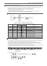
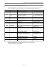
(b) Disconnect sequence
MICRO-EH
3CR
M
odem
Line disconnected
Port communication ends
1]
1] The PLC disconnects the line when the result code “3” is returned from the modem.
Note 1: Since the modem initial setup sets only minimal items from the MICRO-EH side, connect a personal computer
and perform necessary settings before making the connection. (Set the DR signal to always on.) Moreover, do not
change the following initial settings.
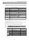
Contents of the initial settings
Command echo: None
Result code: Yes
Display format of result code: Numerical format
Note 2: The modem timeout (WRF03C) stored in the special internal output refers to the time from data transmission
from the MICRO-EH to the data reception from the opposite station (STX, ENQ, NAK). Normally, this special
internal output should be set to “0000” (default) or “H8000” (no timeout). Set the timeout only when it is
especially necessary to monitor the reception time from the opposite station. When a timeout is detected, the
MICRO-EH cuts off the line. When setting the timeout, set the time in the ** part of H80. The unit is * seconds
(hexadecimal).
Note 3: Before actually cutting off the line, issue the task code of the line cut off request (HIC--see Appendix 2, “Task
code list” for details) from the host side.