


Chapter 8 High-speed counter, PWM / Pulse train output and Analogue I/O
8-17
(3) Effective range of PWM output on-duty values
When correcting on-duty values by setting the value that corresponds to the CPU model in the special internal output
(WRF06B) for setting PWM/pulse output correction, the effective range of the on-duty values differs depending on the
frequency and CPU model to be used. The effective range of the on-duty values is calculated from the following
expressions. For the hardware delay time in the expressions, see Table 6.2.
Caution: There will be a slight error even if correction setting is performed.
On-duty lower limit value (%) = Hardware delay time (µs) x Frequency used (Hz) x 10
-4
On-duty upper limit value (%) = 100 - Hardware delay time (µs) x Frequency used (Hz) x 10
-4
Table 8.2 Transistor output delay time for each CPU model
CPU model Hardware delay time (TYP) Remark
EH-***DTP
50 µs
EH-***DT
70 µs
EH-***DRP
75 µs
EH-***DRT
25 µs
Example: If the CPU model is EH-***DRP and the PWM output is 2 kHz,
On-duty lower limit value = 50 x 2000 x 10
-4
= 10 %
On-duty upper limit value = 100 - (50 x 2000 x 10
-4
) = 90 %
Thus, the effective range of on-duty values will be 10 % to 90 %.
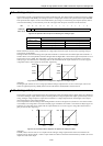
If correction is not performed (0 is set in WRF06B), on-duty values can be set in the range of 0 to 100 %. However,
caution must be exercised since there will be an error for the period of transistor output delay time between the specified
on-duty and the on-duty that is actually output.
(4) Setting abnormality
When the PI/O function setting flag (R7F5) is turned on, and a value exceeding the effective range of on-duty values is
set for the on-duty setting value of each PWM output (WFR076 to WRF079), PWM outputs will not be generated.
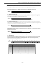
(Example of incorrect setting) PWM output 2 kHz
On-duty setting value (WRF076) - 95
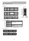
(5) Individual PWM output setting
The frequency and on-duty can be set for each PWM output by the special internal outputs regardless of whether the CPU
is operating or stopped. By setting “H1” in the special internal outputs listed below, it is changed to the frequencies set in
the special internal outputs (WRF072 to WFR075) and the on-duty values set in the special internal outputs (WRF076 to
WFR079). When changing the setting, if any of the on-duty setting values (WRF076 to WRF079) for PWM outputs is set
to a value exceeding the effective range, PWM outputs will not be generated.
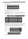
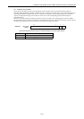
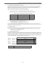
15 2 1 0
WRF058: PWM output 1
Not used a
WRF059: PWM output 2
Not used a
WRF05A: PWM output 3
Not used a
WRF05B: PWM output 4
Not used a
Figure 8.30 Special internal outputs for setting individual PWM outputs
Bit Description
a PWM output: individual setting value change request