


Chapter 3 Function and Performance Specifications
3-11
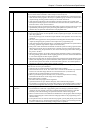
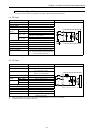
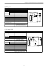
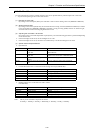
(6) Relay output
Item Specification Circuit diagram
Rated load voltage 5 to 250 V AC, 5 to 30 V DC
Minimum switching current 1 mA
1 circuit 2 A (24 V DC, 240 V AC)Maximum
load current
1 common 5 A
OFF → ON
15 ms (max)
Output
response time
ON → OFF
15 ms (max)
Number of output points See Chapter 4.
Number of common See Chapter 4.
Surge removing circuit None
Fuse None
Insulation system Relay insulation
Output display LED (green)
External connection Removable type screw terminal block (M3)
Externally supplied power
(for driving the relays)
Not necessary
Contact life *1 20,000,000 times (mechanical)
200,000 times (electrical: 2 A)
Insulation 1500 V or more (external-internal)
500 V or more (external-external)
*1: Refer to the Life curve of relay contacts in Chapter 10 for the details.
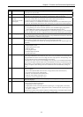
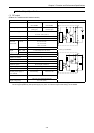
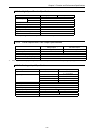
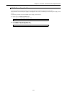
(7) AC output (SSR)
Item Specification Circuit diagram
Output specification Triac output
Rated voltage 100/240 V AC
Output voltage 100 –15 % to 240 +10 % V AC
50 –5 % to 60 +5 % Hz
1 circuit 0.5 A 240 V ACMaximum
load current
1 common 2 A
Minimum load current 100 mA
Maximum leakage current 1.8 mA 115 V AC(max)
3.5 mA 230 V AC(max)
Maximum inrush current 5 A (at 1 cycle or less)/point
10 A (at 1 cycle or less)/common
Off → On
1 ms or less
Maximum
delay time
On → Off
1 ms + 1/2 cycle or less
Output common See Chapter 4.
Polarity See Chapter 4.
Insulation system Phototriac insulation
Fuse *2 Used
Surge removing circuit Sunabar circuit + varistor
External connection Removable terminal block
Voltage drop 1.5 V RMS (max)
Insulation 1500 V or more (external-internal)
500 V or more (external-external)
*2: It is necessary to repair the module if the load short-circuits and causes the fuse to melt.
Note that the fuse cannot be replaced by users.
0
1
C
Internal circuit
0
1
C
Internal circuit