


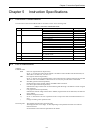

Chapter 5 Instruction Specifications
5-3
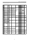
R7F4
R7F3
R7F2
R7F1
R7F0
Process
time
(
µ
s)
Classification
Item number
Ladder symbol
Instruction
symbol
Instruction
name
Process descriptions I/O types used
DERERR SD V C
MICRO-EH
Steps
Remarks
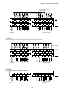
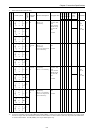
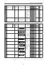
15 MPS MPS Operation
result push
Stores the previous
operation result.
None
zzzzz
—0
16 MRD MRD Operation
result read
Reads the stored operation
result and continues
operation.
17 MPP MPP Operation
result pull
Reads the stored operation
result, continues operation
and clears the stored result.
Sequence instructions
18 ANB Logical
block serial
connection
Indicates serial connection
between two logical blocks.
None
zzzzz
—0
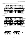
19 ORB Logical
block
parallel
connection
Indicates parallel
connection between two
logical blocks.
None 0.7 1
20 [ ] Processing
box start
and end
Indicates start and end of a
process box.
None
zzzzz
0.6 3
21 ( ) Relational
box start
and end
Indicates start and end of a
comparison box.
None
zzzzz
0.8 0
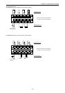
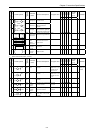
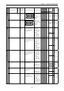
2. Basic instructions (timer, counter)
R7F4
R7F3
R7F2
R7F1
R7F0
Process
time
(
µ
s)
Classification
Item number
Ladder symbol
Instruction
symbol
Instruction
name
Process descriptions I/O types used
DERERR SD V C
MICRO-EH
Steps
Remarks
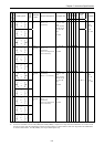
Timer
22
TD
OUT
TD
On delay
timer
Indicates an on delay timer
operation.
TD0 to TD255
When 0.01 s, it is
possible to use
until 0 to 63.
zzzzz
1.4 5 Number
overlap not
allowed
23
SS
OUT
SS
Single shot Indicates a single shot
operation.
SS0 to SS255
When 0.01 s, it is
possible to use 0
to 63.
zzzzz
1.4 5
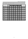
24
CU
OUT
CU
Counter Indicates a counter
operation.
CU0 to CU255
zzzzz
1.4 5
25
CTU
OUT
CTU
Up of
up/down
counter
Indicates an up operation of
up-down counter.
CTU0 to
CTU255
zzzzz
1.4 5
Counter
26
CTD
OUT
CTD
Down of
up/down
counter
Indicates a down operation
of up-down counter.
CTD0 to
CTD255
zzzzz
1.4 3
27
CL
OUT
CL
Counter
clear
Indicates a clear operation
for CU, RCU, CTU, CTD
and WDT.
CL0 to CL255
zzzzz
0.9 1