


Chapter 5 Instruction Specifications
5-130
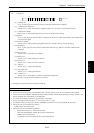
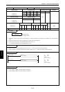
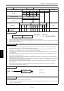
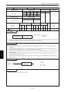
Item number FUN instructions-6 Name High-speed Counter Coincidence Output Control
Ladder format Condition code
Processing time (µs)
Remark
R7F4 R7F3 R7F2 R7F1 R7F0
Average Maximum
FUN 141 (s) DER ERR SD V C
↕
zzzz
Instruction format Number of steps
138
Condition Steps
FUN 141 (s) — 3
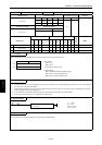
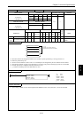
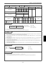
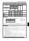
Bit Word Double word
Usable I/O
XY
R,
M
TD, SS,
CU, CT WX WY
WR,
WM TC DX DY
DR,
DM
Constant
Other
s
Argument (Counter
number, output
instruction)
{
Function
Counter number: H01 to H04
Output instruction: H00 – Coincidence output disable,
H01 – Coincidence output able
• Performs the enabling and disabling of the coincidence output for the specified counter.
• Output is turned off when the coincidence output disabling instruction is issued while coincidence output is being performed
(while coincidence output is on).
Notes
• If a value other than H01 to H04 is specified for the counter number and the output instruction is set to a value other than
H00 or H01, DER will be set to “1” and no processing will be performed.
• If the specified counter number is set to a function other than a corresponding external I/O counter (single-phase counter,
two-phase counter), DER will be set to “1” and no processing will be performed.
• Since Counter 4 is invalid when a 10-point CPU is used, if Counter 4 is specified, DER will be set to “1” and no processing
will be performed.
• If the specified counter number is unable to make an output (PI/O function setting result by R7F5), DER will be set to “1”
and no processing will be performed.
• This instruction is only used to enable and disable the coincidence output. Other counter settings will not be changed and it
will not affect the count operation.
• When coincidence output is enabled by this instruction when the coincidence conditions are already established, coincidence
output will be turned on when the instruction is issued.
• The control contents of this instruction will be reflected in the output control flag (R7FC to R7FF) of the corresponding
counter number.
• When the CPU is not operating, the counter coincidence output continues/stops according to the setting of the special
internal output (output selection at R7DC stop).
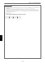
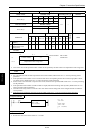
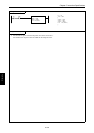
Program example
R1
LD R1
AND DIF1
[
WR1 = H101
FUN 141 ( WR1 )
]
DIF1
WR1 = H0101
FUN 141 (WR1)
Program description
• Sets the coincidence output validity for the counter No. 1.
Because the counter coincidence output Yxxx cannot be used in the ladder program (including the monitor, etc.), do not use
it for the coil such as a contact.
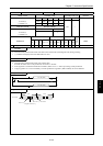
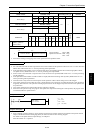
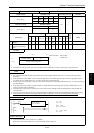
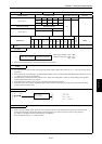
S
Counter number Operation instruction
15 8 7 0
FUN 141 (s)